BIM Manager Scan-to-BIM: Coordination & QC Services

Robotic ImagingApril 3, 2026
BIM Manager Scan-to-BIM: Coordination & QC
For BIM managers coordinating complex renovation projects at educational institutions, the most dangerous coordination gap isn't between design consultants — it's between the new design and unverified existing conditions. Robotic Imaging's bim manager scan to bim services deliver LOD 300–LOD 350 existing conditions Revit models that become the verified baseline for Navisworks clash detection, consultant model quality control, construction milestone verification, and final facility management handoff.
BIM manager scan-to-BIM services provide LOD 300–350 existing conditions Revit models serving as a verified coordination baseline for Navisworks clash detection. The scan model enables new-to-existing conflict identification, quality control of consultant deliverables against scan measurements, construction milestone verification, and scan-verified as-built documentation for facility management handoff — delivered within 10-14 business days.
Educational institutions present some of the most demanding coordination environments in the AEC industry: dense MEP systems in science labs, performing arts acoustic infrastructure, historic building fabric without reliable documentation, and phased construction on occupied campuses with limited access windows. Getting existing conditions wrong at the coordination stage isn't a minor inconvenience — it's the source of the 3–10% change order exposure that erodes construction budgets before a single new pipe is installed.
BIM Coordination Challenges With Unverified Existing Conditions
The gap in most educational renovation coordination workflows isn't between the architect's model and the MEP engineer's model. Navisworks catches that. The gap is between what the consultant assumed about existing conditions and what those conditions actually measure.
When a mechanical engineer routes new ductwork based on as-built drawings that haven't been field-verified, or on dimensions taken from a 1970s set of record drawings, the clash detection model is only as reliable as those inputs. A structural beam documented at elevation +12'-0" on drawings may actually sit at +11'-8" — a 4-inch discrepancy that, in a tight ceiling plenum, renders the entire ductwork routing coordination invalid.
BIM managers at educational institutions encounter this problem consistently across three scenario types:
Historic buildings: Pre-1980 construction rarely has dimensional documentation within coordination tolerances. Record drawings reflect design intent, not built reality. Walls are thicker, columns are offset, floor-to-floor heights vary by wing.
Multi-consultant environments: When four or five consultant teams (architect, structural, MEP, AV, IT infrastructure) are each modeling against the same assumed existing conditions baseline, dimensional errors compound. Each team's model is internally consistent but collectively inaccurate against the building.
Phased campus renovation: Limited access windows mean conditions may be documented during one mobilization and construction doesn't begin for 18 months. Without a scan-verified baseline, that 18-month gap introduces unverified assumptions into every coordination decision.
Robotic Imaging's bim coordination services resolve this by replacing assumed existing conditions with a registered point cloud baseline — verified to ±1/16 inch using the LEICA RTC 360 — from which the existing conditions Revit model is built. Every consultant model then coordinates against a geometrically true representation of the building.
> Ready to address your existing conditions coordination gap? Request BIM Coordination Documentation to review deliverable specifications and QC methodology before your next RFQ.
Coordination Workflow Integration: Scan Model as Navisworks Baseline
The practical value of a scan-based existing conditions model is determined by how cleanly it integrates into the federated coordination workflow BIM managers are already running. A model that requires extensive rework to meet project Revit standards, or a point cloud delivered in an incompatible format, creates friction that undermines the accuracy investment.
Robotic Imaging delivers existing conditions models in two complementary formats for BIM coordination workflows:
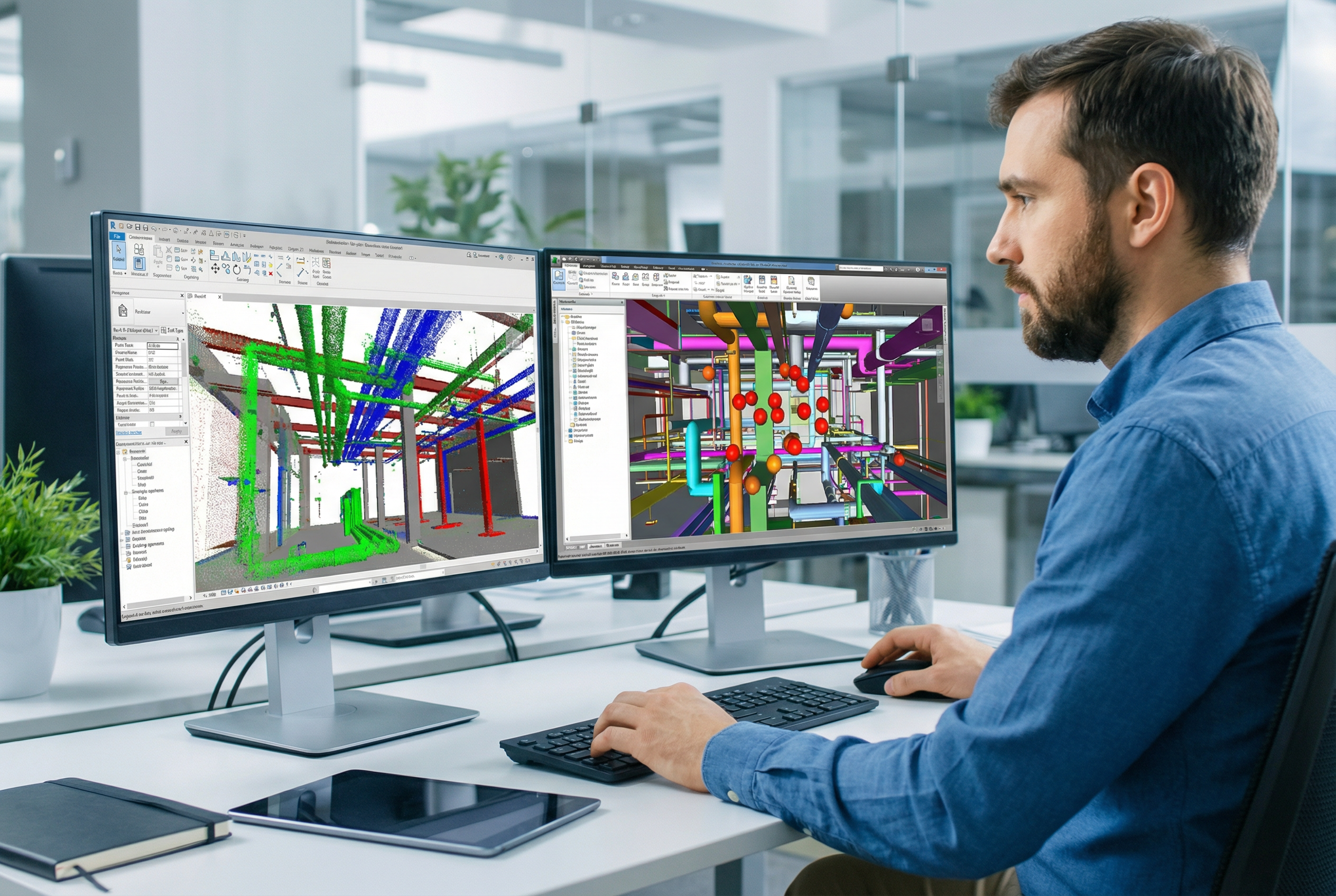
Revit .rvt model (LOD 300–350): Structured by discipline (architectural, structural, MEP) and organized to federate directly into Navisworks NWC/NWD workflows. The model follows the project's workset structure and coordinate system, so it imports without transformation into the federated model alongside consultant design files.
Point cloud RCS/RCP files: Registered point cloud data referenced directly into Revit for consultant overlay and visual verification. MEP engineers can draft new routing against the actual scan data — not just the modeled interpretation — and verify clearance dimensions in real-time before coordination meetings.
The clash detection scanning workflow functions in three stages:
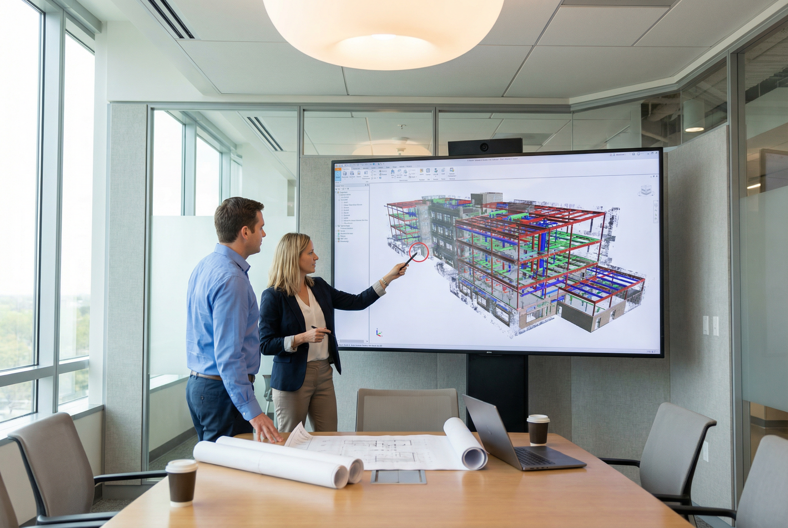
Stage 1 — New-to-existing clash identification: The scan-based existing conditions model is federated into Navisworks alongside new design models. Clash detection runs between new design elements and verified existing conditions, catching conflicts that would never appear in a new-to-new clash matrix. In a representative educational renovation scenario, this stage has surfaced structural beam conflicts that would have required field rerouting of primary ductwork runs — conflicts invisible to teams working from unverified drawings.
Stage 2 — Consultant model QC against scan baseline: Individual consultant models are compared against the point cloud baseline to verify dimensional alignment. An MEP engineer who modeled an existing 12-inch pipe at a different elevation than the scan data shows creates a coordination conflict that needs correction before the federated model is valid. BIM managers use the point cloud RCS/RCP files to run this verification independently, without waiting on consultant model corrections.
Stage 3 — Coordination meeting efficiency: When all consultants are coordinating against a verified baseline, meetings shift from debating whether existing conditions are accurate to resolving actual new-to-new and new-to-existing design conflicts. This is the operational dividend of bim coordination scanning — not just better models, but faster, more decisive coordination meetings.
The bim manager laser scanning workflow timeline delivers field capture in 2-3 days, point cloud processing in 3-5 days, and BIM modeling in 7-10 days — Revit .rvt and RCS/RCP deliverables in hand within 10-14 business days before your design coordination meeting schedule requires them.
LOD Selection for Coordination: 300 vs. 350 Decision Framework
Not every existing condition in an educational renovation requires the same Level of Development. Applying LOD 350 universally increases cost and modeling time without proportional coordination value. The LOD selection decision should be driven by clash detection risk, not uniform specification.
LOD 300 — Architectural and Structural Systems
LOD 300 is appropriate for existing conditions where ±2-inch dimensional tolerance is acceptable and new design elements have sufficient clearance buffer. This covers:
- Exterior envelope, exterior wall assemblies
- Structural grid, column locations, slab edges
- Interior partitions in open areas with generous ceiling heights
- Stair cores, elevator shafts, mechanical chases
At LOD 300, the LEICA BLK 360 (±1/4 inch accuracy) provides sufficient precision for modeling, and the modeling investment is calibrated to coordination risk.
LOD 350 — Dense MEP Systems and Tight Ceiling Spaces
LOD 350 is required wherever MEP routing, connection geometry, or support structure must be coordinated within tight tolerances. In educational buildings, this specifically includes:
- Science lab ceiling plenums with multi-trade density (HVAC, lab exhaust, plumbing, electrical conduit, data)
- Mechanical rooms and air handling unit areas
- Kitchen and food service infrastructure
- Performing arts rigging and acoustic equipment zones
At LOD 350, existing pipe routing, duct geometry, conduit runs, and support hangers are all modeled with connection-level detail. Clash detection at this resolution catches 1–2 inch conflicts that determine whether new systems can route through available plenum space.
For LOD 350 MEP coordination, Robotic Imaging deploys the LEICA RTC 360 — rated at ±1/16 inch accuracy, capturing 2,000,000 points per second — which provides the scan density and positional precision to model existing MEP geometry at LOD 350 with confidence. Competitors who reference generic "laser scanners" without specifying accuracy tolerances cannot make this claim verifiably.
The practical LOD decision framework for BIM managers:
| Space Type | Recommended LOD | Justification |
|---|---|---|
| Open classroom / office | LOD 300 | Low MEP density, generous clearances |
| Corridor / circulation | LOD 300 | Primarily structural reference |
| Science lab / research | LOD 350 | Dense MEP, tight plenum coordination |
| Mechanical / electrical room | LOD 350 | Routing and connection-level detail required |
| Auditorium / gymnasium | LOD 300 (structure), LOD 350 (MEP) | Hybrid by system |
Quality Control & Consultant Model Verification
Delivering a scan-based existing conditions model is necessary but not sufficient for coordination quality control. Model quality control documentation — the process by which consultant Revit models are verified against scan data — is where most scan-to-BIM providers leave BIM managers without support.
Robotic Imaging's QC methodology operates at two levels:
Level 1 — Scan-to-model dimensional verification: Before delivery, every existing conditions Revit model is verified against the registered point cloud for dimensional accuracy. Key verification checkpoints include:
- Structural element elevations (beams, columns, slabs) checked at representative grid intersections
- MEP system centerlines verified against point cloud measurements at coordination-critical locations
- Wall face dimensions verified for partition alignment and opening geometry
This verification is documented as a QC report delivered alongside the Revit model, providing BIM managers with written evidence of model accuracy verification — not just an assertion of accuracy.
Level 2 — Consultant model QC support: The point cloud RCS/RCP files delivered alongside the Revit model give BIM managers an independent verification tool. When a consultant delivers a model that conflicts with the scan baseline — for example, an MEP engineer modeling an existing 24-inch duct at a centerline elevation that differs from scan data by 8–12 inches — the BIM manager can document that deviation against the scan record and require correction before the model enters the federated coordination set.
In a representative educational renovation scenario, this second-level QC process has caught MEP contractor deviations where existing equipment was modeled based on catalog dimensions rather than field measurement, producing conflicts that would have surfaced as costly field rework rather than model corrections. Frame that as the coordination risk that scan-verified QC prevents, not just a modeling inconvenience.
bim coordination services from providers who deliver only a model file — without QC documentation or point cloud deliverables for independent verification — leave BIM managers without the tools to enforce consultant model accuracy. The RCS/RCP files are not optional supplementary data; they are the QC instrument.
Robotic Imaging has documented over 100 million square feet across commercial, institutional, and AEC client projects — including work with Colliers Engineering and Nelson Worldwide. The QC methodology applied to those engagements is the same process applied to educational renovation coordination projects, regardless of project scale.
As-Built Verification During Construction Milestones
Scan-to-BIM value doesn't end at pre-design existing conditions documentation. For BIM managers managing educational renovation construction, milestone scanning during construction phases provides a second layer of coordination protection: verifying that what was built matches what was modeled before subsequent trades build on top of it.
The milestone scanning workflow operates on the same 10-14 business day cycle:
- MEP rough-in milestone: Scan ductwork, piping, and conduit rough-in before ceiling grid installation. Verify installed geometry against LOD 350 coordination model. Document deviations for contractor record and clash detection update.
- Structural steel milestone: Scan structural frame after erection but before MEP rough-in begins. Verify beam and column geometry against structural coordination model. Flag any bearing or elevation deviations that affect MEP routing assumptions.
- Pre-ceiling closure milestone: Final scan before ceilings close. Produce scan-verified as-built record of all concealed systems for facility management handoff.
The value of milestone scanning in educational renovation is particularly significant because of the occupied campus context. When construction is phased around academic calendars, deviations discovered after a ceiling is closed — in a corridor that won't be accessible again for 18 months — have outsized remediation cost compared to deviations caught at the rough-in milestone.
Model accuracy verification at each milestone also provides contractor accountability documentation that red-lined drawings cannot match. When a contractor claims a deviation was within tolerance, the milestone scan provides millimeter-level dimensional evidence of actual installed position versus coordination model position.
Robotic Imaging supports milestone scanning with the same 24/7 scheduling system and 2-3 day field capture timeline used for pre-design documentation — mobilizing within access windows dictated by academic calendar constraints rather than requiring contractors to accommodate scanning schedules.
Facility Management Handoff: Scan-Verified As-Built Models
The final milestone scan — post-construction, pre-occupancy — produces the scan-verified as-built model that defines the quality of facility management documentation for the life of the building. Educational institutions with 50–100 year building lifecycles have a direct operational interest in as-built accuracy that exceeds what most commercial real estate owners require.
A scan-verified as-built BIM model at LOD 300–350 serves as the existing conditions baseline for the next renovation cycle — compressing pre-design documentation timelines, eliminating re-scanning of unchanged systems, and providing facilities staff with dimensional confidence for routine maintenance planning.
The contrast with red-lined drawing as-builts is significant: red-lines document what contractors reported, not what was installed. When a mechanical upgrade requires routing a new chilled water line through a mechanical room, the difference between a scan-verified model showing actual pipe centerlines and a red-lined drawing showing approximate routing can determine whether the project goes through one RFI or twenty.
Robotic Imaging's as-built documentation workflow integrates milestone scan data from construction phases into the final deliverable, producing an as-built model that reflects verified installed conditions at every documented milestone — not a post-construction model assembled from contractor submittals and field observations.
Conclusion: BIM Manager Coordination Workflow Best Practices
For BIM managers at educational institutions, the coordination workflow that prevents change order exposure and produces reliable FM documentation follows a consistent logic: verify existing conditions before design, coordinate new design against verified baseline, verify construction against coordination model at milestones, and hand off scan-verified as-built documentation for the building's operational life.
Robotic Imaging's bim manager scan to bim services cover every phase of that workflow:
- Pre-design: LEICA RTC 360 field capture → registered point cloud → LOD 300–350 Revit .rvt + RCS/RCP deliverables in 10-14 business days
- Coordination: Navisworks-compatible model structure, QC documentation, point cloud for independent consultant model verification
- Construction: Milestone scanning on 2-3 day capture cycles, deviation documentation, contractor accountability records
- FM handoff: Scan-verified as-built model as next-cycle existing conditions baseline
The scan-to-BIM investment for a $10M–$50M educational renovation represents less than 1% of construction value. The change order exposure from unverified existing conditions — documented in the 3–10% range across comparable renovation programs — makes that baseline investment the highest-ROI coordination decision a BIM manager can make before design development begins.
Frequently Asked Questions
What LOD is required for BIM coordination and clash detection? LOD 300 is appropriate for architectural and structural coordination with ±2-inch tolerance requirements. LOD 350 is required for MEP coordination in dense ceiling plenums, mechanical rooms, and lab environments where routing and connection-level detail determines clash detection reliability.
How does scan-to-BIM improve Navisworks clash detection workflows? A scan-based existing conditions model adds a verified existing conditions layer to the federated Navisworks model, enabling new-to-existing clash detection in addition to new-to-new coordination. It also provides the point cloud RCS/RCP baseline for verifying consultant model accuracy before federation.
How do BIM managers verify consultant model accuracy against existing conditions? Point cloud RCS/RCP files delivered alongside the Revit model allow BIM managers to independently verify consultant model geometry against scan data. Dimensional deviations can be documented and corrections required before models enter the federated coordination set.
Ready to build your verified coordination baseline?
- Request Coordination Quote — Provide project scope for a customized proposal with LOD specification and timeline
- Schedule a Coordination Workshop — 60-minute technical session with Robotic Imaging's BIM coordination team to map scan deliverables to your Navisworks workflow
- Download the BIM Manager Guide — LOD decision framework, QC checklist, and milestone scanning workflow reference for educational renovation projects