Clash Detection in Construction: How LiDAR Scanning Eliminates Design Conflicts
Robotic ImagingJune 3, 2026
Clash Detection in Construction: How LiDAR Scanning Eliminates Design Conflicts
Clash detection in construction is the process of identifying spatial conflicts between design elements before they cause problems in the field. Using LiDAR-derived BIM models analysed in Navisworks, AEC teams locate hard clashes, soft clashes, and workflow conflicts at the design stage — eliminating costly rework, change orders, and construction delays before a single structural element is placed or a duct is run.
Design conflict coordination has become a standard requirement on renovation and new construction projects where MEP systems, structural elements, and architectural components must occupy the same tightly constrained space. Robotic Imaging delivers clash detection as part of its Clash Detection services, using LEICA RTC 360 Laser Scanning at ±2mm accuracy to produce the precise BIM models that make meaningful clash analysis possible.
What Is Clash Detection in Construction?
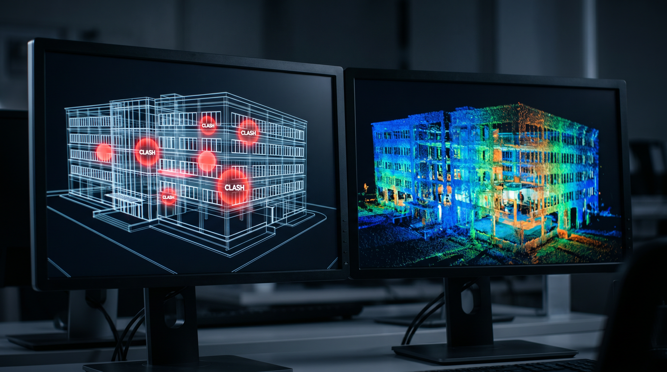
Clash detection in construction is the automated or manual review of a BIM model to find instances where two or more design elements occupy the same physical space — or where spacing is insufficient for safe installation, maintenance, or operation. The process is typically run inside Autodesk Navisworks using a federated BIM model that combines structural, architectural, and MEP disciplines into a single coordinated model.
Without this analysis, conflicts between these disciplines surface only when crews reach that phase of construction — at which point resolving the issue means stopping work, ordering redesigns, and absorbing the cost of materials already installed incorrectly. Industry data consistently shows that construction change orders — many of which originate from undiscovered clashes — add 5–15% to total project costs on complex commercial and renovation projects.
The foundation of accurate conflict identification is accurate existing-conditions data. On renovation projects where existing building systems are already in place, a LiDAR scan of the existing conditions gives the design team a verified starting point rather than assumptions drawn from outdated drawings.
Three Types of Clash Detection Every AEC Team Needs to Understand
Three distinct categories of construction conflict exist, each requiring a different resolution approach.
Hard Clashes
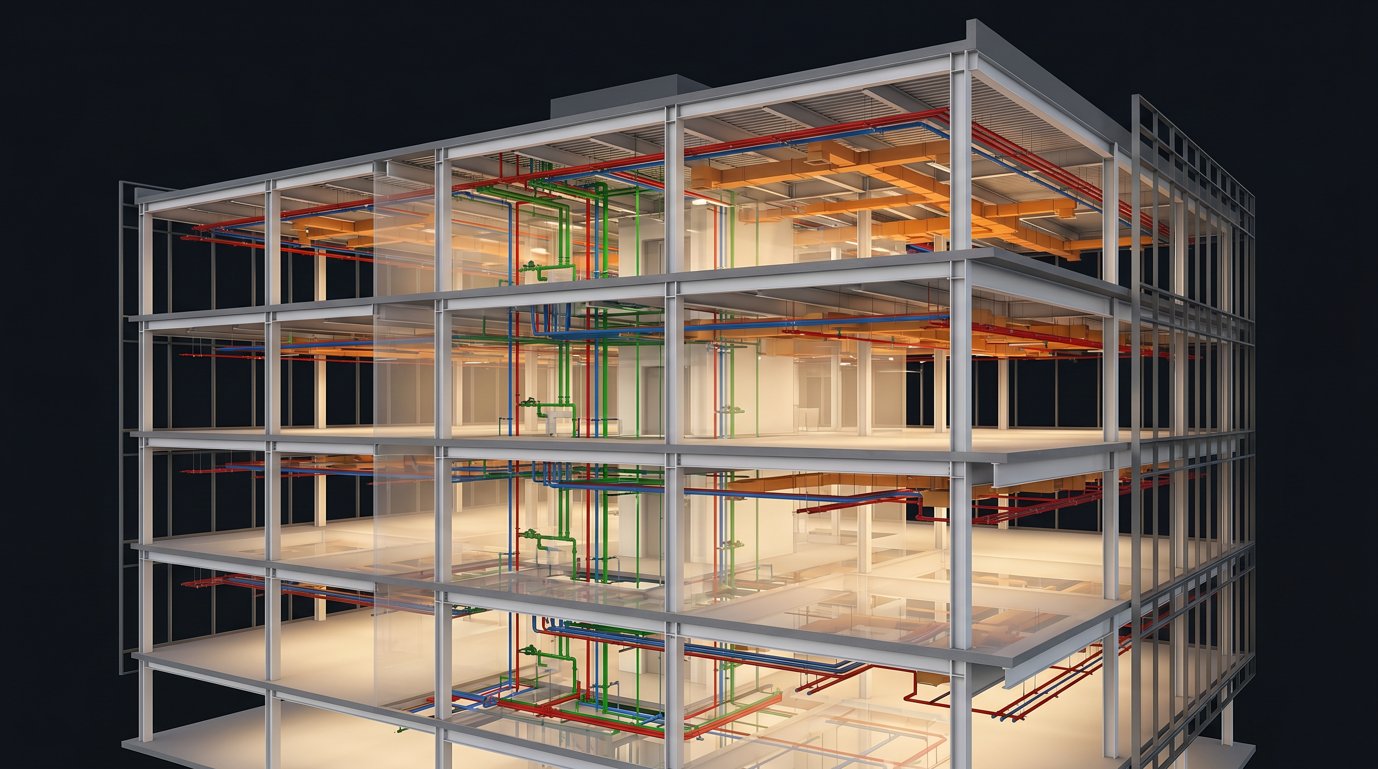
A hard clash occurs when two elements physically overlap in the model — the most critical type. Examples include a ductwork run intersecting a structural beam, a plumbing riser passing through a column, or an electrical conduit routed through a wall framing member. Hard clashes represent a physical impossibility: the design, as drawn, cannot be built without modification.
Soft Clashes
A soft clash occurs when elements don't physically intersect but violate required clearance tolerances. A mechanical unit installed with insufficient service access, an electrical panel positioned too close to a structural element for code-compliant clearance, or a pipe run that leaves inadequate room for insulation are all soft clashes. These are often harder to catch manually than hard clashes.
Workflow Clashes
Workflow clashes expose inconsistencies in scheduling or information flow — a trade scheduled to complete rough-in before the preceding trade has finished, or conflicting specifications across different design disciplines for the same element. These clashes don't show up in spatial analysis but create coordination failures that delay construction.

How Clash Detection in Construction Works with LiDAR Scanning
Meaningful conflict detection depends entirely on the quality of the BIM model it runs against. A model built from inaccurate existing-conditions data — or from drawings that don't reflect what was actually built — will miss real-world clashes and generate false positives for clashes that don't actually exist. This is where LiDAR scanning is decisive.
Robotic Imaging captures existing building conditions using LEICA RTC 360 scanners that produce Point Clouds at 2,000,000 points per second with ±2mm accuracy across 130-meter ranges. That Point Cloud becomes the geometric foundation of the BIM model. When MEP engineers and architects then design new systems against that model, they are designing against verified existing conditions — not assumptions.
The workflow connects directly to Scan-to-BIM production: the registered Point Cloud is modeled in Autodesk Revit at the required Level of Development — typically LOD 300 or LOD 350 for coordination work — then the federated model is exported into Navisworks where clash rules are defined and the automated detection sweep is run. The result is a prioritised clash report identifying every conflict by type, location, and severity.
What Does Clash Detection in Construction Actually Prevent?
The business case for LiDAR-based BIM coordination rests on quantifiable cost avoidance. On commercial renovation and retrofit projects, the most common and expensive problems it prevents include:
- Construction change orders — accurate MEP coordination resolves conflicts before construction, cutting change orders by 15–25% on complex renovation projects
- Schedule delays — field discoveries that require trade sequencing changes stop work and cascade across the project timeline
- Material waste — ductwork, pipe, and conduit fabricated to incorrect dimensions based on undetected clashes becomes scrap
- Rework labour costs — cutting out and reinstalling already-placed systems is among the highest-cost construction activities
- Regulatory non-compliance — soft clashes that violate code-required clearances can require redesign and re-inspection even after construction completes
On large commercial renovation projects, a single undetected MEP hard clash discovered in the field can trigger days of stoppage across multiple trades simultaneously. The cost of resolving that clash in Navisworks during design is measured in hours of modeler time; the cost of resolving it in the field is measured in stopped crews, redesign fees, and expedited material orders.
The LiDAR-Based Clash Detection Workflow for Commercial Projects
Conflict detection is not a standalone deliverable — it is the output of an integrated Robotic Imaging workflow that begins with LiDAR field capture and concludes with a clash-resolved, construction-ready BIM model. The process follows a consistent sequence:
LiDAR Field Capture (2–3 Days)
Robotic Imaging deploys LEICA RTC 360 scanners to document existing building conditions from multiple positions, producing a complete registered Point Cloud of all visible structural, architectural, and MEP elements. Field crews are dispatched within 2–3 days of project authorization.
Scan-to-BIM Conversion (7–10 Days)
The registered Point Cloud is modeled in Autodesk Revit at LOD 300 or LOD 350 — with geometric tolerances of ±1/4 inch at LOD 300 and ±1/16–1/8 inch at LOD 350 — capturing walls, floors, columns, ceilings, and all visible MEP systems. Output files are delivered in RVT, IFC, or NWC format for direct import into Navisworks. View representative deliverables in Robotic Imaging's 3D model gallery.
Clash Detection Analysis
The federated BIM model — combining the as-built scan model with new design disciplines — is run through Navisworks to identify spatial conflicts. Hard, soft, and workflow clash rules are configured to match project-specific tolerances and clearance requirements. The output is a prioritised clash report with each conflict georeferenced to its exact location in the model.
Resolution and Updated Delivery (10–14 Days Total)
Identified clashes are reviewed with the design team, resolutions are modeled, and the detection sweep is re-run to confirm clearance. The final clash-resolved BIM model is delivered within 10–14 business days of project authorization, at Scan-to-BIM pricing from $0.19/sqft.
Clash Detection in Construction vs. Traditional Coordination Methods
Before LiDAR-enabled BIM coordination became standard, AEC teams relied on 2D drawing overlays and manual review sessions to identify clashes. The limitations of that approach are significant compared to model-based BIM coordination.
| Factor | Traditional 2D Coordination | LiDAR + BIM Clash Detection |
|---|---|---|
| Clash identification | Manual, prone to human error | Automated, comprehensive sweep |
| Existing conditions data | Assumed from as-built drawings | Verified ±2mm LiDAR Point Cloud |
| 3D conflict detection | Limited, Z-axis often missed | Full 3D spatial analysis |
| Speed advantage | Baseline | 50–80% faster than manual methods |
| Soft clash detection | Rarely caught before field | Configurable clearance tolerances |
The Laser Scanning services that underpin BIM coordination also produce the Scan-to-CAD deliverables used for permit drawings and contractor coordination packages — so the same field capture session supports multiple downstream uses.
Resolve Design Conflicts Before They Reach the Field
Robotic Imaging delivers LiDAR-based Scan-to-BIM and conflict coordination services from $0.19/sqft with a 10–14 business day turnaround. LEICA RTC 360 at ±2mm accuracy. ISO 27001 certified and SOC 2 Type II compliant.
Get a Free QuoteFrequently Asked Questions About Clash Detection in Construction
What is clash detection in construction?
Clash detection in construction is the automated or manual review of a federated BIM model to identify spatial conflicts between design elements — structural, architectural, and MEP — before construction begins. It uses software like Navisworks to find hard clashes (physical overlaps), soft clashes (insufficient clearances), and workflow clashes (scheduling or data conflicts).
Why is LiDAR scanning used for clash detection?
LiDAR scanning provides verified existing-conditions data at ±2mm accuracy, giving the BIM model a reliable geometric foundation. Without accurate existing-conditions data, clash detection may miss real-world conflicts or flag false positives for clashes that don't exist. LiDAR eliminates the guesswork that occurs when designers work from outdated or assumed as-built drawings.
What are the three types of clashes in BIM?
The three types are hard clashes (two elements physically occupying the same space, such as a duct intersecting a beam), soft clashes (elements that don't physically overlap but violate required clearance tolerances for maintenance or code compliance), and workflow clashes (scheduling or information inconsistencies between project disciplines).
How much does clash detection reduce construction change orders?
Accurate MEP coordination through BIM conflict analysis reduces construction change orders by 15–25% on complex renovation and retrofit projects. Change orders triggered by field-discovered clashes — which require design revisions, material reorders, and rework — represent some of the highest-cost items on commercial construction projects.
What software is used for clash detection in construction?
Autodesk Navisworks is the primary clash detection platform used in commercial AEC. It accepts federated BIM models from Revit, combines multiple disciplines, and runs automated conflict detection sweeps with configurable rules for hard and soft clash tolerances. Clash reports are exported showing each conflict's location, type, and severity.
How long does LiDAR-based clash detection take?
Robotic Imaging's full workflow — LiDAR field capture, Scan-to-BIM modeling, conflict analysis, and delivery — completes within 10–14 business days from project authorization. Field capture takes 2–3 days, Point Cloud processing 3–5 days, and BIM modeling and coordination 7–10 days.
All pricing, delivery timelines, accuracy specifications, and client references reflect verified data from roboticimaging.com as of June 2026. Robotic Imaging is ISO 27001 certified and SOC 2 Type II compliant.