MEP Engineer Scan-to-BIM for Renovation Coordination
Robotic ImagingApril 8, 2026
MEP Engineer Scan-to-BIM for MEP Coordination
For MEP engineers designing renovation systems into existing facilities, the ceiling space above your tiles is effectively a black box. Drawings from the original construction — or the last renovation — rarely reflect what was actually built, and almost never capture subsequent modifications. The ductwork trunk got rerouted. An electrical conduit run was added during a tenant improvement. A structural beam that isn't on any drawing is sitting exactly where your new VAV box needs to go.
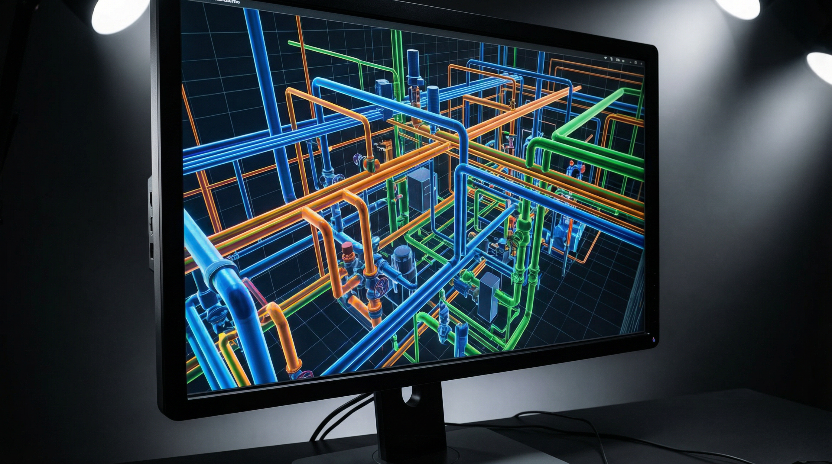
MEP engineer scan-to-BIM services from Robotic Imaging address this problem directly: capturing the complete above-ceiling environment with survey-grade laser scanning equipment, then delivering LOD 350 Revit models that document every duct, pipe, conduit, fitting, support hanger, and structural constraint in the ceiling plenum — with ±2-4mm accuracy sufficient for fabrication-grade tie-in coordinates.
MEP Coordination Challenges in Renovation Projects
MEP engineer scan-to-BIM provides LOD 350 documentation of existing mechanical, electrical, and plumbing systems including above-ceiling spaces — capturing complete ductwork routing with sizes and elevations, conduit and piping paths, structural constraints, and precise tie-in coordinates. The resulting Revit model enables clash detection in Navisworks and fabrication-grade coordination, eliminating field conflicts and change orders during construction.
That definition matters because what it replaces — existing drawings, field sketches, and manual tape measurements — is consistently unreliable as a design basis for renovation work. The consequences compound quickly: a duct that's 4 inches lower than shown on drawings shifts your design clearances. A beam that isn't in the structural model means your new chilled water main can't route where you planned. Tie-in coordinates estimated from drawing geometry rather than actual field conditions put fabricated spools in the wrong location.
These aren't edge cases. In occupied facilities with decades of modifications, the gap between as-drawn and as-built conditions is the norm. Robotic Imaging's MEP coordination scanning workflow closes that gap before design development commits you to decisions that will fail in construction.
Facing unknown above-ceiling conditions on your next renovation? Request MEP Coordination Documentation from Robotic Imaging.
Above-Ceiling Documentation Scope
Above-ceiling scanning for mechanical coordination is the systematic capture of the full ceiling plenum using laser scanning equipment — not a sampling approach, not a spot-check of proposed tie-in locations. The entire ceiling space is documented: every system, every constraint, every structural element, in a single field campaign.
Mechanical systems documented include:
- Supply and return air ductwork — main trunks, branches, transitions — with exterior dimensions, centerline elevations, and routing geometry
- VAV boxes, fan coil units, unit ventilators, and associated flex connections
- Duct insulation thickness (affecting clearance calculations)
- Hydronic piping — chilled water, hot water, condenser water mains and branch runouts with pipe diameter and elevation
- Condensate drain lines and slope geometry
- Mechanical equipment supports and vibration isolators
Electrical documentation scope includes:
- Cable tray systems — width, depth, routing, support intervals
- Conduit runs by trade (power, data, fire alarm) — diameter, routing path, junction boxes
- Panel locations and feeder routing above ceiling
- Lighting circuit conduit and junction box locations
Plumbing system capture covers:
- Domestic cold and hot water mains and branches
- Sanitary and vent lines — diameter, slope, cleanout locations
- Medical gas piping where applicable — oxygen, vacuum, nitrogen lines at correct diameter and elevation
Structural constraints — frequently absent from working drawings — are captured in full:
- Structural steel beams, bar joists, and kickers
- Concrete deck soffits and drop beams
- Existing MEP penetrations through structural members
- Fire damper locations and clearance zones
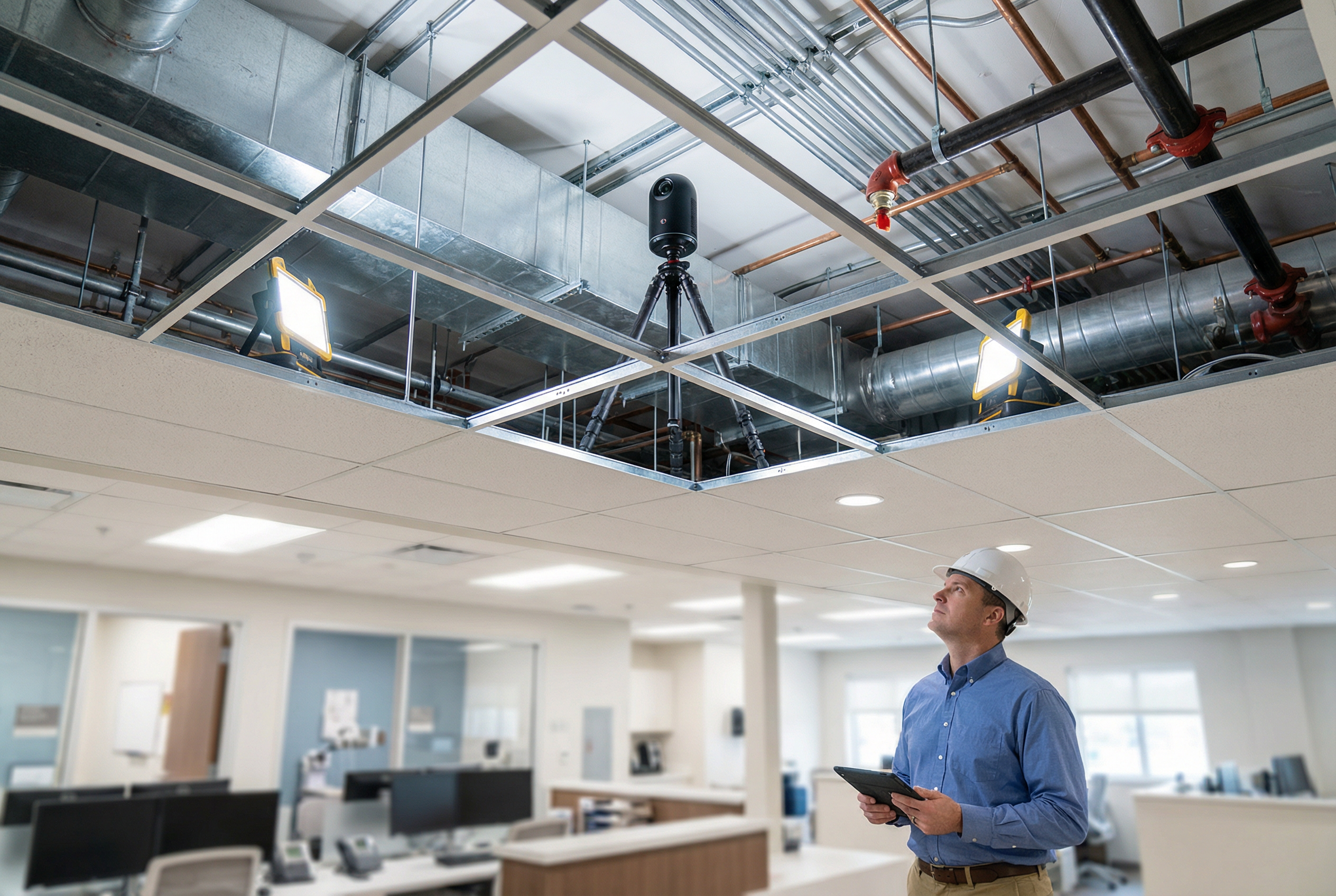
Equipment and methodology for above-ceiling access:
The LEICA RTC 360 captures 2,000,000 points per second at ±1/16 inch accuracy, producing the point density required to resolve fittings, reducer couplings, and hanger bracket geometry at sub-millimeter resolution. For systematic above-ceiling documentation in occupied bays — particularly healthcare environments where tile removal must be coordinated carefully — the LEICA BLK 360 provides a compact form factor ideally suited to scanning within the ceiling plenum with minimal disturbance to adjacent spaces. For large mechanical rooms and central plant documentation, the ScanStation P40 delivers survey-grade accuracy at 270m range, capturing equipment pads, pipe racks, and header assemblies in a single setup sequence.
Tile removal follows a systematic protocol: tiles are lifted, the scanner is positioned, and capture occurs before moving to the next bay. In occupied clinical environments, this sequence is coordinated with facilities operations to restrict access only to the active scan area at any point in time.
LOD 350 MEP Deliverable Specifications
LOD 350 is the appropriate deliverable target for MEP coordination on renovation projects — and it's meaningfully different from LOD 300. Where LOD 300 documents system routing and approximate geometry, LOD 350 captures the interface information required for coordination: how systems connect to each other, what space they actually occupy, and what clearances other trades must respect.
For mechanical, electrical, and plumbing documentation, the LOD 350 deliverable from Robotic Imaging includes:
Ductwork (LOD 350):
- Rectangular and round duct modeled to exterior dimensions (not centerlines only)
- Duct fittings: elbows, transitions, tees, wyes, offsets — each modeled as a distinct element
- Duct accessories: dampers, access doors, turning vanes at correct locations
- Insulation modeled as separate element (affects clearance verification)
- Hanger locations and support rod attachment points
- Connection interface at diffusers, VAV boxes, and terminal units
Piping (LOD 350):
- Pipe runs modeled at correct diameter, elevation, and routing geometry
- Fittings: elbows, tees, reducers, unions — modeled individually
- Valves, strainers, and flow meters at correct locations
- Pipe insulation as separate element
- Hanger spacing and support rod geometry
- Tie-in interface coordinates with ±2-4mm spatial accuracy
Conduit and Cable Tray (electrical BIM modeling):
- Conduit runs at correct diameter and routing path
- Conduit bodies, junction boxes, and pull boxes at correct locations
- Cable tray modeled to actual width and depth with fill indication
- Tray fittings: elbows, tees, reducers, covers
Revit deliverable specifications:
- File format: Revit (.rvt), compatible with current release
- Point cloud formats available: RCS, RCP, E57, LAS
- Navisworks-ready NWC/NWD export for immediate clash detection federation
- Revit families: standard MEP families with verified geometry; custom families for non-standard equipment where required
The LOD 350 Revit model is structured to federate directly into your MEP design model. Robotic Imaging delivers the as-built model as a linked file — your new design systems overlay directly onto existing conditions, enabling clash detection in Navisworks without additional processing or conversion.
MEP Coordination Workflow
The coordination workflow runs sequentially from field capture through fabrication support:

Phase 1 — Field Capture (2-3 days): Above-ceiling scanning is executed using the LEICA RTC 360 and LEICA BLK 360 in a systematic scan position sequence. Scan positions are registered to a unified coordinate system referenced to building control points, ensuring the point cloud aligns to your project coordinate system. Total field time for a typical floor plate ranges 1-3 days depending on ceiling grid density and access complexity.
Phase 2 — Point Cloud Processing (3-5 days): Raw scan data is registered, quality-checked, and processed into a unified point cloud. Accuracy verification is performed against control points. The processed point cloud is available as a project reference deliverable (RCS, E57, LAS) alongside the BIM model.
Phase 3 — BIM Modeling (7-10 days): The LOD 350 Revit model is built from the registered point cloud. Modeling follows the deliverable scope defined above: all systems, all fittings, structural constraints, and support geometry. Model review includes internal QC against the point cloud before delivery.
Total timeline: 10-14 business days from field mobilization to LOD 350 Revit deliverable.
MEP clash detection integration: Once the as-built model is delivered, the coordination workflow in Navisworks proceeds as follows:
1. Federation: Link the as-built model (existing conditions) and the new design model into a single Navisworks federated model 2. Clash detection run: Execute automated clash detection — hard clashes between new systems and existing constraints, clearance clashes against maintenance access zones 3. Clash review: Clash report identifies specific conflicts by element pair, location, and severity 4. Design adjustment: New MEP routing modified in Revit before fabrication drawings are issued 5. Fabrication coordination: With clashes resolved in the model, spool drawings reflect actual field geometry — tie-in coordinates from the point cloud are embedded in the model at ±2-4mm accuracy
This workflow eliminates the field-fit assumption that drives change orders. Traditional approaches — working from existing drawings with field-measured spot checks — leave tie-in coordinates at ±1/2 inch or worse. At that tolerance, fabricated spools require field modification. At ±2-4mm, direct fabrication from model geometry is achievable.
Ceiling Space Analysis
The above-ceiling space is not simply a routing zone — it's a shared constraint environment where structural geometry, existing MEP systems, new MEP systems, clearance envelopes, and access requirements all compete for the same volume. Ceiling space analysis maps this competition before design locks in.
Routing zone mapping: The LOD 350 model enables routing zone mapping — the process of identifying which horizontal bands of ceiling space are available for new systems, which are obstructed by existing systems, and where structural constraints create hard limits. This analysis is most directly useful during schematic design, when routing decisions are still flexible.
Typical discoveries in ceiling space analysis that affect routing decisions:
- An existing HVAC trunk running at an elevation 6 inches lower than shown on drawings — compressing the available routing zone for new systems beneath the structural deck
- A structural beam at an existing column line not shown on drawings — blocking a proposed routing corridor
- Existing conduit banks occupying the only clear horizontal zone for a new chilled water main
Equipment clearance verification: The LOD 350 model documents clearance envelopes around existing equipment — VAV boxes, fan coil units, fire damper access panels — that must be maintained for maintenance access. New system routing that violates these clearances creates a field coordination conflict regardless of whether it shows as a hard clash in Navisworks. The model captures these clearance zones as modeled elements, enabling visual verification without running separate clearance clash rules.
Finished ceiling elevation confirmation: In renovation projects where finished ceiling height is being modified, the point cloud provides the actual structural deck elevation and existing MEP system elevations — the two constraints that bound the design zone. Ceiling height decisions made without this data frequently compress the MEP routing zone in ways that aren't apparent until construction begins.
Healthcare Facility MEP Coordination
Healthcare renovation projects concentrate every challenge of above-ceiling MEP documentation into the most demanding operational environment: occupied clinical spaces, infection control requirements, restricted access windows, and HVAC systems where pressure relationships are critical to patient safety.
Phased construction approach: Healthcare MEP coordination scanning operates in phases coordinated with clinical operations. Robotic Imaging's 24/7 scheduling availability enables scanning during off-hours windows — nights and weekends — when clinical areas can be vacated temporarily without disrupting care delivery. The compact LEICA BLK 360 scanner is particularly suited to this application: its smaller footprint and rapid repositioning speed enable a full bay to be scanned during a single off-hours access window.
For facilities teams coordinating MEP scanning with occupied floor operations, Robotic Imaging's project visibility dashboard provides real-time scan progress tracking — enabling clinical operations scheduling to coordinate around active scan zones rather than working from estimated completion timeframes.
Infection control HVAC documentation: In healthcare facilities, HVAC system modifications carry patient safety implications that don't exist in commercial renovation. Pressure relationship documentation — positive pressure in operating rooms, negative pressure in isolation rooms — requires accurate documentation of existing duct configurations, volume damper positions, and exhaust system routing before any modification is designed. The LOD 350 model captures these elements at the fidelity required to assess modification impacts on pressure relationships.
Representative scenario — the value of pre-design scanning: Consider a hospital renovation project where the design team is working from original construction drawings with hand-marked redlines from a previous renovation. An above-ceiling scan reveals a structural beam at an elevation 18 inches lower than shown in the structural drawings — directly intersecting the proposed chilled water main routing. Discovery during design development, before fabrication drawings are issued, enables a routing modification that eliminates a potential $60,000+ change order scenario. Discovery during construction, after the spool is fabricated, does not.
This is the consistent pattern that makes pre-design MEP coordination scanning the standard approach for healthcare renovation on any project where above-ceiling conditions are a design variable.
AEC firm workflow integration: Engineering firms including Colliers Engineering and Nelson Worldwide have integrated Robotic Imaging's scan-to-BIM deliverables into MEP design workflows. The LOD 350 Revit model format is structured for direct federation with MEP design models — existing conditions as a linked file, new design on top, Navisworks clash detection ready without conversion or reformatting. For MEP engineers at firms with established Revit MEP templates, the deliverable is designed to integrate without workflow modification.
Getting Started: MEP Coordination Quote
The complete MEP coordination scan-to-BIM workflow runs from field capture through LOD 350 Revit delivery in 10-14 business days: 2-3 days of systematic above-ceiling documentation using LEICA RTC 360 and LEICA BLK 360 equipment, 3-5 days of point cloud processing and registration, and 7-10 days of LOD 350 BIM modeling including all MEP systems, structural constraints, fittings, supports, and tie-in interface geometry. The delivered Revit model is Navisworks-ready for immediate clash detection federation with your new MEP design model.
Robotic Imaging provides nationwide US coverage for healthcare facilities, laboratories, data centers, and complex commercial renovations — the occupied facility environments where above-ceiling conditions are most likely to diverge from existing drawings and where the cost of discovery during construction is highest. Over 100 million square feet of documented building area reflects the operational capacity to handle multi-floor, multi-phase MEP documentation programs without extending your project schedule.
Ready to eliminate above-ceiling uncertainty from your next renovation?
- Request MEP Coordination Quote — provide project address, approximate square footage, and project schedule; receive a scoped proposal within 2 business days
- Schedule an Engineering Consultation — 30-minute technical call to review above-ceiling access requirements, LOD 350 deliverable scope, and Revit template coordination before scoping
- Contact Robotic Imaging — for multi-phase healthcare renovation programs requiring phased scanning coordination with clinical operations scheduling
Facing tie-in coordinate uncertainty, unknown above-ceiling obstructions, or clash detection failures from inaccurate existing conditions data? Get a customized quote for MEP scan-to-BIM documentation tailored to your facility type and coordination workflow. Contact Robotic Imaging today.