Scan-to-BIM Deliverables: LOD 300-400 | Verified Standards
Robotic ImagingMarch 11, 2026
Scan-to-BIM Deliverable Specifications and Quality Standards
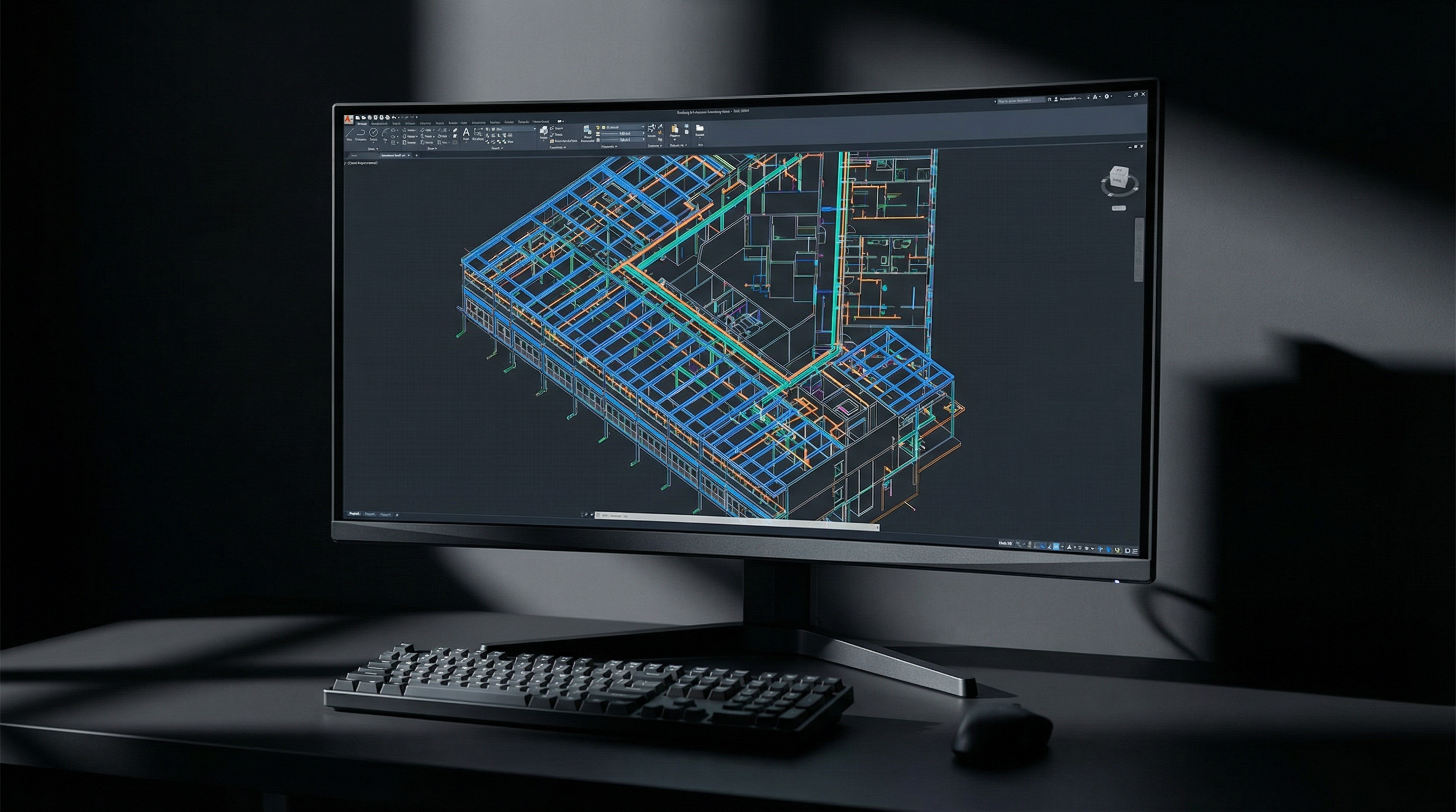
Robotic Imaging's Scan-to-BIM deliverables include Revit native files (.rvt) at specified Level of Development (LOD 200, 300, 350, or 400), Point Cloud formats (RCS, RCP, E57, LAS), 2D CAD drawings (.dwg), IFC files for interoperability, Navisworks NWC for clash detection, and optional 360° virtual tours. Each deliverable type carries specific accuracy standards — from ±1/16 inch with LEICA RTC 360 equipment to ±1/4 inch with LEICA BLK 360 — and must be specified upfront to prevent post-delivery quality issues that cascade into rework costs and schedule delays.
Scan-to-BIM deliverables at the wrong LOD, in the wrong file format, or with misaligned coordinate systems are among the most common — and most expensive — problems BIM Managers encounter when onboarding scan data from external vendors. Defining specifications before scanning begins is not optional; it determines whether the deliverable integrates into your project workflow or requires reconstruction from scratch.
The following specification framework covers everything required to evaluate scan-to-BIM deliverables against project requirements — and serves as the technical foundation for Robotic Imaging's documented delivery standards across 100+ million square feet of commercial documentation for enterprise clients including JLL and Colliers Engineering.

Why Deliverable Specifications Matter Before Scanning Begins
The most expensive scan-to-BIM errors are not modeling mistakes — they are specification mismatches discovered after final delivery. A Revit model built in version 2023 delivered to a firm running 2021 creates conversion overhead that can corrupt families and views. An E57 point cloud delivered where RCS/RCP was required forces re-registration inside Autodesk software. A model built to LOD 200 where LOD 350 was expected means structural connections, MEP routing, and equipment clearances are missing entirely.
These issues share a common cause: deliverable specifications were never locked in writing before the project began.
For BIM Managers evaluating scan-to-BIM vendors, the quality of a vendor's deliverable specification process is itself a quality signal. Vendors who ask detailed questions about Revit version, LOD requirements, coordinate system preferences, and metadata fields before quoting are vendors who understand what they are producing. Vendors who quote without asking these questions will often deliver without meeting them.
Scan-to-BIM deliverables include, at minimum, the following components — each requiring explicit specification:
- Revit BIM Model (.rvt): LOD level, Revit version, family types, view/sheet organization, metadata fields
- Point Cloud: Format (RCS, RCP, E57, LAS), coordinate system, density/registration accuracy
- 2D CAD Drawings (.dwg): Floor plans, elevations, sections, drawing organization
- Supplemental Formats: IFC, NWC, PDF, 360° virtual tour (project-dependent)
Revit BIM Model Specifications
The Revit BIM model is the primary deliverable for most commercial office scan-to-BIM projects, and it carries the most specification variables. Getting these right before the project begins prevents the majority of post-delivery revision requests.
LOD Level Content Differences
Level of Development defines what is modeled, not just how accurately. The AIA/USIBD LOD Framework governs standard definitions:
- LOD 200: Generic elements with approximate size, shape, and location. Suitable for early design studies and space programming. Walls, floors, and ceilings modeled as generic assemblies without specific material or assembly attributes.
- LOD 300: Elements modeled with specific quantity, size, shape, location, and orientation. This is the standard baseline for construction coordination and renovation design. Wall assemblies, door/window schedules, structural grid, and MEP equipment locations are modeled to dimension-verified specifications.
- LOD 350: LOD 300 geometry plus interface and connection information sufficient for coordination with other building systems. MEP routing modeled with clearances, structural connections shown, penetrations located. This is the working standard for complex commercial renovation and tenant improvement projects.
- LOD 400: Fabrication-level detail. Elements modeled to size, shape, location, quantity, and orientation with fabrication, assembly, and installation information. Required for prefabrication coordination and detailed construction documentation.
Robotic Imaging delivers LOD 300 and LOD 350 as standard commercial office deliverables, with LOD 400 available for MEP coordination projects requiring fabrication-level accuracy. LOD level is confirmed in writing at project kickoff — not assumed from project type.
Revit Version Compatibility
Revit files cannot be opened in versions older than the version in which they were saved. A model saved in Revit 2023 cannot be opened in Revit 2021 without third-party conversion, which frequently disrupts family assignments, view configurations, and sheet organization.
Robotic Imaging confirms client Revit version before modeling begins and delivers in the client's current working version. Supported delivery versions include Revit 2020, 2021, 2022, and 2023. This is specified in the project scope document — not discovered at handoff.
Family Types, Views, and Metadata
Beyond geometry, a production-ready Revit model requires:
- System families for walls, floors, ceilings, and roofs modeled to match existing assembly types
- Loadable families for doors, windows, equipment, and fixtures with correct category assignments for scheduling
- View organization: Floor plan views, reflected ceiling plans, elevations, and sections organized by level with consistent view naming conventions
- Sheet organization: Title block, drawing list, and standard view placement matching client template requirements (template files accepted and applied on request)
- Metadata fields: Room names, room numbers, department assignments, and equipment tags populated for FM handoff workflows — confirmed against client requirements before delivery
Point Cloud Format Options
Point cloud format selection is determined by downstream software, not vendor preference. The three primary formats each serve distinct use cases:
RCS and RCP (Autodesk Native)
RCS (Reality Capture Scene) and RCP (Reality Capture Project) are Autodesk's native point cloud formats, optimized for direct use in Revit, AutoCAD, Civil 3D, and Navisworks. RCS files contain individual scan positions; RCP files are container files that reference multiple RCS files as a unified project.
- When to specify: Any workflow using Autodesk software as the primary platform
- Advantages: Direct load into Revit with no conversion; cloud point rendering optimized for Autodesk viewport performance
- Limitations: Proprietary format — limited compatibility outside Autodesk ecosystem
E57 (Universal Standard)
E57 is the ASTM international standard for point cloud data exchange, supported by virtually all major scan processing and BIM software platforms including Revit, Bentley, Trimble, and Leica Cyclone.
- When to specify: Multi-platform workflows, cross-firm data sharing, archival standards, or any project where long-term format accessibility matters
- Advantages: Universal compatibility; preferred for file archiving and multi-vendor coordination
- Limitations: Requires import/conversion step in some Autodesk-native workflows
LAS (Survey and GIS Applications)
LAS is the standard format for geospatial and civil engineering point cloud data, used in GIS platforms (Esri ArcGIS), civil design software (Bentley, Trimble), and survey data management systems.
- When to specify: Site survey applications, campus documentation integrated with civil drawings, infrastructure projects, or any workflow involving GIS data
- Advantages: Native compatibility with survey and civil software; supports intensity and RGB data alongside XYZ coordinates
Coordinate System Options
Point cloud coordinate systems must be specified before field capture — they cannot be reliably changed after scan registration without quality loss. Two primary options apply to commercial office projects:
- Project Coordinates: Relative to a project benchmark (typically a building corner or survey monument). Standard for single-building documentation without site integration requirements.
- Georeferenced Coordinates: GPS-tied to real-world coordinate systems (State Plane, UTM). Required for campus documentation, civil integration, or multi-building portfolio projects where models must merge at a site level.
Robotic Imaging's LEICA ScanStation P40 supports survey-grade georeferenced capture with ground control point (GCP) documentation included in the deliverable package when georeferencing is specified.
2D CAD Drawings and Supplemental Formats
For projects where Revit is not the primary working environment, or where 2D documentation supplements the BIM model, as-built file formats in the .dwg standard provide full compatibility with AutoCAD and most downstream architectural and engineering workflows.
AutoCAD DWG Drawings
2D CAD deliverables extracted from the scan-to-BIM workflow include:
- Floor plans at each level with dimensioned room layouts, door/window locations, and column grid
- Elevations of primary interior and exterior faces
- Sections through key areas as specified in project scope
- Reflected ceiling plans (RCP) with ceiling heights and lighting layout
- Layer organization following AIA layer standards or client-specified conventions
DWG files are delivered in AutoCAD 2018 format by default, with client-specified version available on request.
IFC (Industry Foundation Classes)
IFC files support open-standard BIM data exchange across platforms that do not use Revit natively — including Bentley OpenBuildings, Archicad, and FM systems such as Archibus, Planon, and IBM TRIRIGA. IFC export from the Revit model preserves geometry, spatial hierarchy, and object classification data.
- When to specify: Facility management platform integration, non-Autodesk design workflows, owner BIM requirements specifying open-standard formats
Navisworks NWC for Clash Detection
Navisworks NWC files allow the scan-to-BIM model to be loaded directly into Navisworks Manage for clash detection, 4D scheduling, and model review without requiring a Revit license on every coordination team workstation.
- When to specify: Multi-trade coordination projects, design-build workflows, construction phasing review
360° Virtual Tours
Robotic Imaging delivers browser-accessible 360° virtual tours alongside point cloud and BIM deliverables for projects where visual documentation of existing conditions supplements the dimensional record. Virtual tours are navigable by floor plan, require no software installation, and provide timestamped photographic documentation of pre-construction conditions.
Quality Standards and Verification Process
BIM quality specifications without a documented verification process are promises, not guarantees. Robotic Imaging's QC methodology operates at three stages before final deliverable release:
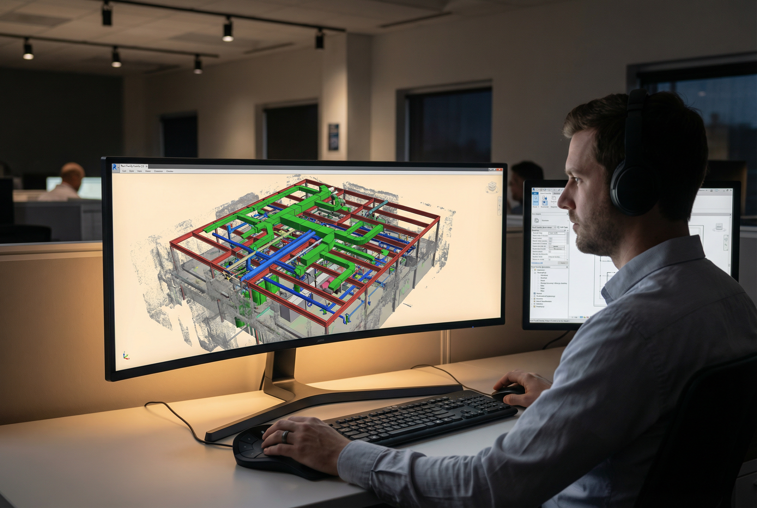
Stage 1 — Field Capture Verification: Scan registration is validated in the field before the crew demobilizes. Overlap between scan positions is confirmed, control point placement is documented, and accuracy targets are met per equipment specification: ±1/16 inch with the LEICA RTC 360 for precision office documentation, ±1/4 inch with the LEICA BLK 360 and BLK 2 for standard commercial applications, and survey-grade accuracy with the ScanStation P40 for large campus or georeferenced projects.
Stage 2 — Modeling QC Checklist: Before draft delivery, each Revit model is checked against the point cloud for dimensional accuracy across primary building dimensions, room clearances, structural grid, and MEP routing (at LOD 350). Category organization, view completeness, family assignment, and metadata field population are verified against the project scope specification.
Stage 3 — Draft Review and Revision Round: Draft deliverables are released via Robotic Imaging's web dashboard for client review. One structured revision round is built into the standard delivery process. Revision requests are tracked against the original scope specification to distinguish scope-covered revisions from scope additions.
Total delivery timeline from field capture to final approved deliverable: 10-14 business days, broken down as 2-3 days field capture, 3-5 days point cloud processing and registration, and 7-10 days BIM modeling and QC. Enterprise clients including JLL and Colliers Engineering rely on this timeline for project scheduling integration across commercial portfolio documentation programs.
File Delivery and Getting Started
Final scan-to-BIM deliverables are delivered through Robotic Imaging's cloud-based project dashboard — accessible by client team members with role-based permissions, with version history, delivery confirmation tracking, and direct download for all file formats. No FTP setup or large file transfer service coordination required.
Deliverable specification is confirmed in writing at project kickoff through a structured scope document covering LOD level, Revit version, point cloud format, coordinate system, metadata requirements, and supplemental format inclusions. This document serves as the QC benchmark against which draft deliverables are reviewed.
Ready to define your scan-to-BIM deliverable specifications? Request a deliverable specification consultation with Robotic Imaging to confirm format requirements, LOD targets, and timeline fit for your next commercial project — or request sample deliverables at LOD 300 and LOD 350 to evaluate modeling depth before committing to a project scope. Contact Robotic Imaging to get started.