Industrial Scan-to-BIM | LOD Standards | Robotic Imaging
Robotic ImagingJune 23, 2026
Scan-to-BIM for Industrial Facilities: LOD Standards and Deliverable Guide
Scan-to-BIM for industrial facilities converts LiDAR point clouds of manufacturing plants, warehouses, and process facilities into Revit models at LOD 200–400. For most industrial renovation and MEP coordination projects, LOD 300–350 delivers exact geometry and connection detail. Fabrication-grade scopes — structural steel, custom equipment pads, process piping — typically require LOD 400.
For capital project managers overseeing factory renovations, equipment installations, or plant acquisitions, inaccurate as-built drawings are the single largest source of field change orders and budget overruns. Manual survey methods cannot reliably capture the dimensional complexity of industrial environments — multi-level process equipment, dense MEP runs, structural steel, and equipment pads — at the tolerances engineering teams require before design begins. Robotic Imaging's industrial Scan-to-BIM service eliminates that dimensional uncertainty with scanner-grade field capture, in-house Revit modeling, and delivery in 10–14 business days.
What Is Scan-to-BIM for Industrial Facilities?
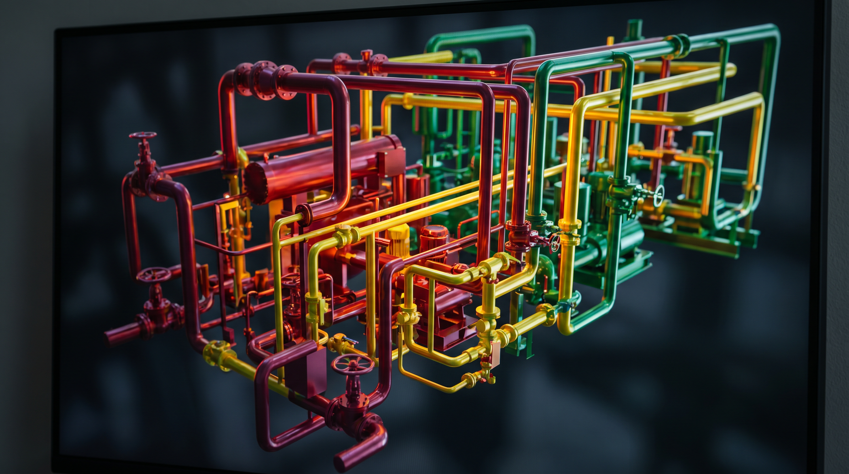
Scan-to-BIM for industrial facilities is the process of capturing an existing manufacturing plant, warehouse, or process facility using LiDAR laser scanning equipment, then converting that point cloud data into a parametric BIM model inside Revit at a specified LOD. The resulting model documents existing conditions with measurable, verifiable accuracy — not estimates derived from tape measures or manual field sketches.
Industrial environments present documentation challenges that commercial or institutional buildings rarely match: open floor plates measuring hundreds of meters, dense overhead MEP and process piping, structural steel at irregular intervals, heavy equipment with complex geometry, and multi-level mezzanine systems. Traditional surveying methods struggle with these conditions both for speed and accuracy. Laser scanning captures complete spatial geometry simultaneously, producing millions of measured data points per second that become the foundation for every dimension in the BIM model.
The workflow moves in three stages: field capture using calibrated LiDAR scanners, point cloud registration and processing using Autodesk ReCap Pro, and LOD-specific BIM modeling in Revit. Each stage has defined quality control checkpoints. The output is a Revit model that reflects actual as-built conditions — not design intent — at whichever LOD your project requires.
LOD Standards for Industrial BIM: Which Level Does Your Project Need?
LOD selection is the most consequential decision at the start of any industrial Scan-to-BIM project. Under-specifying LOD leaves coordination gaps that surface as change orders during construction. Over-specifying LOD 400 for a project that only requires renovation documentation adds cost and timeline without adding value. The framework below maps each LOD to its appropriate industrial project trigger.
| LOD Level | Model Characteristics | Industrial Use Case | Typical Project Trigger |
|---|---|---|---|
| LOD 200 | Mass and shape, general size and location | Facility programming, space planning, M&A due diligence | Plant acquisition, portfolio documentation, feasibility studies |
| LOD 300 | Exact geometry, accurate dimensions and location | Renovation design, as-built verification, GC coordination | Facility retrofit, capital project pre-construction, code compliance |
| LOD 350 | Interfaces and connections between systems, trade coordination detail | MEP coordination, multi-trade clash detection, system retrofit | MEP retrofit, process piping tie-in, multi-contractor coordination |
| LOD 400 | Fabrication-ready, full assembly and manufacturing detail | Structural steel shop drawings, CNC fabrication, equipment support steel | Custom equipment installation, structural steel fabrication, process piping fabrication |
Decision guidance: LOD 300–350 is the standard deliverable for most industrial Scan-to-BIM projects. If your project requires existing conditions for renovation design, MEP system coordination, or multi-trade clash detection, specify LOD 350. If the model will directly drive CNC fabrication, structural steel shop drawings, or custom equipment support steel, specify LOD 400. For M&A documentation or early feasibility where approximate massing is sufficient, LOD 200 delivers faster turnaround at lower cost. When in doubt, Robotic Imaging's project engineers can review your scope and confirm the appropriate LOD before mobilization.
Industrial Scan-to-BIM Deliverables by LOD Level
Understanding what you physically receive at each LOD prevents misaligned expectations between the project manager, engineering team, and general contractor. Robotic Imaging structures industrial deliverable packages around the LOD specified at project scoping, with the following standard inclusions at each level.
LOD 200 deliverables include a Revit model with massed building elements, general equipment locations, and approximate structural geometry. This LOD is suitable for programming documents, M&A due diligence reports, and early capital planning studies. File formats: .rvt, .DWG, and point cloud in RCS or E57.
LOD 300 deliverables include a fully dimensioned Revit model with accurate floor plans, sections, elevations, structural elements, equipment footprints, and primary MEP routing. Industrial-specific elements captured at LOD 300 include equipment pads and bases, structural column grids and roof framing, primary process piping mains, overhead electrical conduit mains, and HVAC/mechanical unit locations. 2D CAD output (.DWG, .DXF) is included as standard.
LOD 350 deliverables add interface and connection detail to the LOD 300 foundation — pipe flanges and fittings, conduit junction boxes and pull points, structural connections, HVAC duct branch connections, and equipment connection points. This level enables NavisWorks clash detection across all modeled trades before construction begins.
LOD 400 deliverables include every element at fabrication-ready detail: weld symbols on structural steel, bolt patterns on equipment supports, exact pipe spool geometry, and full assembly detail for custom-fabricated components. This LOD is appropriate only when the Revit model will directly generate fabrication documents or drive CNC manufacturing processes. All deliverables include the raw point cloud in RCS, RCP, E57, or LAS format depending on your downstream software environment.
Equipment Selection for Industrial Laser Scanning: Why Hardware Accuracy Matters
Scanner hardware is not interchangeable. The accuracy specification of the scanner deployed in the field determines the accuracy ceiling of every dimension in the resulting Revit model. For industrial capital projects where a 5mm dimensional error can compound across a 200-meter process line into significant positional offset, scanner selection is an engineering decision — not a logistics one.
Robotic Imaging fields the following scanner hardware for industrial Scan-to-BIM projects, matched to site conditions during project scoping:
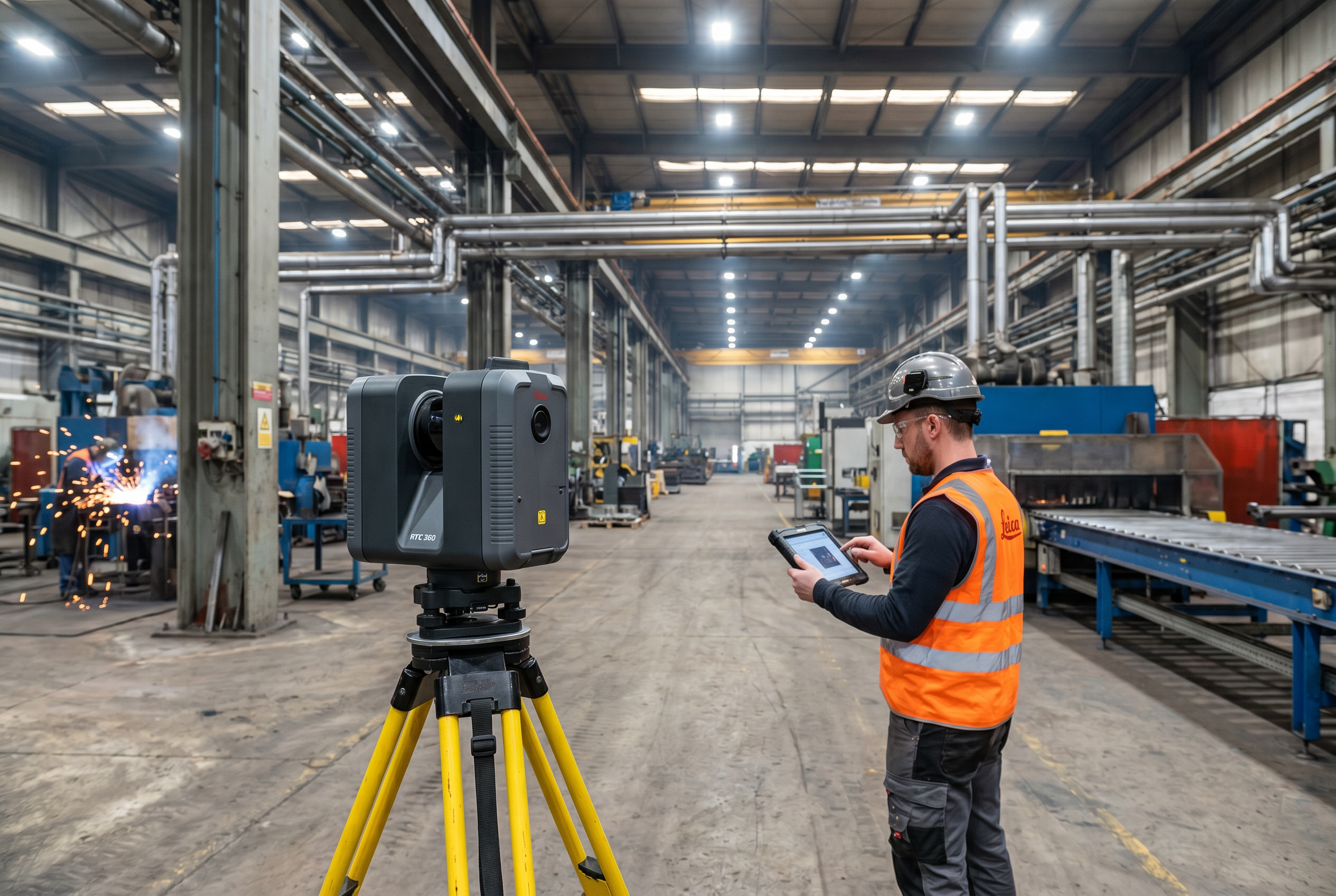
LEICA RTC 360 — 2,000,000 points per second capture rate, ±2mm accuracy, 130m range, IP54 dust and splash protection. This is Robotic Imaging's primary scanner for large open manufacturing floor plates, multi-level process equipment environments, and warehouse facilities. The IP54 rating makes it appropriate for industrial environments with dust or moisture exposure. The 130m range allows comprehensive coverage of large industrial bays from a minimal number of scan positions, reducing capture time and registration complexity.
LEICA BLK 360 G2 — 360,000 points per second, ±4mm at 10m, 60m range. Applied in confined mechanical rooms, tight equipment spaces, and areas where the RTC 360 cannot be positioned due to access restrictions. The compact form factor accesses spaces that larger tripod-mounted scanners cannot reach.
LEICA BLK2GO — 420,000 points per second, mobile walk-through scanner. Used for continuous capture around complex process equipment geometry and industrial corridors without repeated static setups. Particularly effective for documenting dense equipment arrangements where static scanner positioning would require excessive setups.
LEICA ScanStation P50 — Survey-grade accuracy. Applied for structural and engineering survey applications, large industrial site perimeters, and projects requiring certified survey-grade point cloud data.
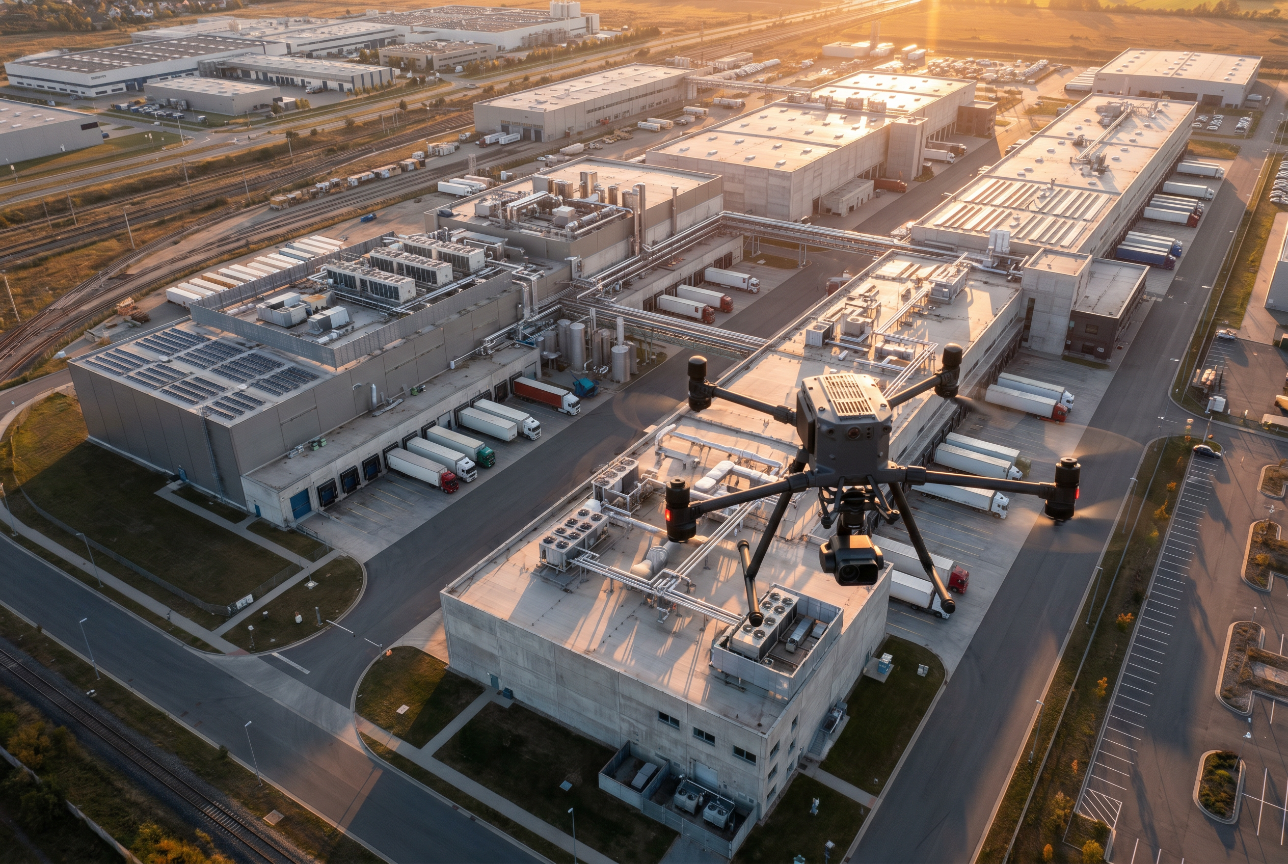
DJI Matrice 300 RTK and DJI Mavic 3 Enterprise — Exterior facade documentation, roof surveys, and large-area industrial site perimeter capture. All aerial operations are conducted by FAA Part 107 certified operators.
Industrial BIM Workflow: From Field Capture to Revit Deliverable
Robotic Imaging's industrial Scan-to-BIM workflow runs in three sequential phases with defined handoffs and quality review at each stage. Total delivery from field capture to final Revit model is 10–14 business days — 50–80% faster than traditional manual survey and BIM drafting workflows for comparable industrial facilities.
Phase 1: Field Capture (2–3 Days On Site)
The field team mobilizes with the scanner hardware matched to your facility's conditions during scoping. Scan setup positions are planned to achieve overlapping point cloud coverage across all target areas — manufacturing floor, mezzanine levels, mechanical rooms, exterior perimeters. Registration targets are placed to enable accurate point cloud stitching in processing. Multi-floor facilities and complex industrial geometry typically require denser scan position grids to eliminate shadow zones behind equipment. All scan data is quality-checked on site before the team demobilizes.
Phase 2: Point Cloud Processing via ReCap Pro (3–5 Days)
Raw scan data is registered and cleaned using Autodesk ReCap Pro. Registration aligns all individual scan positions into a unified, georeferenced point cloud. Noise filtering removes false returns from reflective surfaces common in industrial environments — polished equipment housings, glass panels, and metallic surfaces. The processed point cloud is reviewed against accuracy thresholds before BIM modeling begins. Output formats at this stage: RCS and RCP for Revit workflow; E57 and LAS for non-Autodesk platforms.
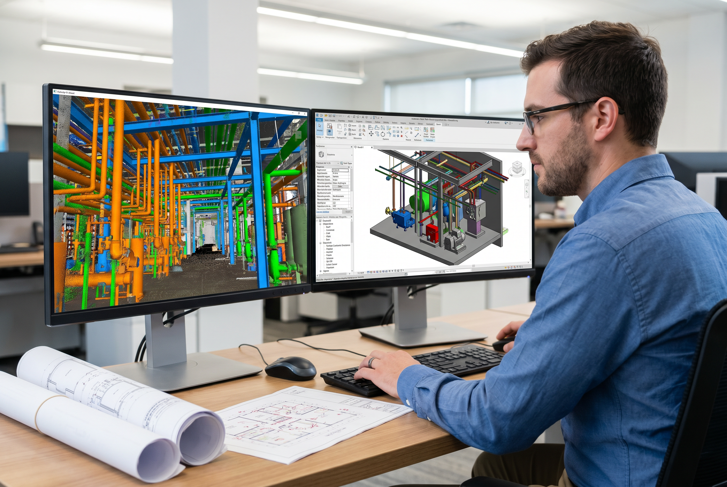
Phase 3: BIM Modeling in Revit (7–10 Days)
Robotic Imaging's in-house BIM team models all facility elements from the verified point cloud at the specified LOD. Every dimension in the Revit model traces back to a measured point cloud return — not an estimated field measurement. Industrial-specific modeling includes structural systems, equipment geometry, MEP routing, process piping, and architectural envelope. A QA review compares the completed model against the point cloud before delivery. The final deliverable package includes the .rvt Revit file, 2D CAD drawings, and the processed point cloud in the formats specified at scoping.
Scan-to-BIM Applications in Industrial Facilities: MEP, Fabrication, and Renovation
Scan-to-BIM for industrial facilities serves a range of capital project types, each with distinct LOD and deliverable requirements. Robotic Imaging has deployed industrial Scan-to-BIM programs for manufacturing clients including Metalwërks, Puratos Inc., and The Plant — representative of the industrial facility types and project scopes our team handles across process manufacturing, food production, and mixed-use industrial environments.
MEP coordination and clash detection. Industrial MEP retrofits involve adding new mechanical, electrical, or plumbing systems into a facility with existing infrastructure that may or may not be accurately documented. LOD 350 Revit models capture every existing pipe run, conduit main, duct system, and structural member with interface and connection detail sufficient for NavisWorks clash detection before any contractor mobilizes. Catching a pipe routing conflict in NavisWorks costs a modeling revision; catching it in the field costs a change order, a delay, and a subcontractor dispute.
Capital equipment installation. Installing new production equipment — presses, conveyors, chillers, compressors — requires precise knowledge of existing structural capacity, equipment pad dimensions, utility connection locations, and clearance envelopes. LOD 400 Scan-to-BIM models provide the exact as-built geometry needed for equipment pad design, anchor bolt layout, and utility tie-in design without field verification trips by the equipment supplier's engineering team.
Production line relocation. Relocating or reconfiguring a production line requires a complete existing-conditions record of the current layout before any design work begins. LOD 300 Scan-to-BIM captures the current equipment arrangement, structural grid, and utility infrastructure at a level sufficient for re-layout design without multiple site visits by the design team.
Facility acquisition and M&A documentation. Pre-acquisition facility documentation at LOD 200 gives real estate and capital planning teams a spatial record of the facility's structural systems, floor areas, and major equipment before close. This enables accurate capital improvement budgeting and integration planning without relying on legacy as-built drawings that may be decades out of date.
Pre-construction documentation for renovation GC coordination. LOD 300 Scan-to-BIM models give general contractors accurate existing-conditions data before renovation design is finalized — reducing RFI volume during construction and providing a conflict-resolution reference when field conditions differ from design assumptions.
How Does Industrial Scan-to-BIM Reduce Change Orders and Rework?
Inaccurate as-built drawings are the primary source of field change orders on industrial renovation and retrofit projects. When design is based on manual field sketches, tape-measure dimensions, or legacy drawings that have not been updated through decades of facility modifications, the design model reflects what the facility was supposed to be — not what it actually is. The gap between assumed and actual conditions is resolved in the field, at contractor rates, after work has already been scheduled.
Scan-to-BIM eliminates this gap by replacing assumed dimensions with measured ones. The LEICA RTC 360's ±2mm capture accuracy means that every structural column, pipe run, duct section, and equipment pad in the Revit model is positioned to within 2mm of its actual location. There is no dimensional uncertainty carried into design — only verified geometry.
At LOD 350, the model includes interface and connection detail between building systems and structural elements — the information required to detect trade conflicts before construction begins. Running a NavisWorks clash detection analysis against an LOD 350 Scan-to-BIM model surfaces pipe-to-structure conflicts, duct-to-equipment clearance violations, and conduit routing collisions in the model environment, where they cost a modeling revision to resolve. Finding the same conflicts in the field — after ductwork has been hung, conduit has been run, or structural steel has been installed — costs a combination of field labor, materials, contractor overhead, and schedule delay that a model revision cannot approach.
Robotic Imaging delivers industrial Scan-to-BIM with the scanner-grade accuracy, LOD precision, and in-house quality review that capital project teams require to protect their project budgets at the pre-construction stage.
Choosing a Scan-to-BIM Provider for Industrial Projects: What to Evaluate
Industrial Scan-to-BIM is a specialized service. Not every provider that offers commercial Scan-to-BIM can deliver the scanner hardware specifications, data security posture, or in-house BIM modeling depth that industrial capital projects require. The following criteria apply specifically to industrial facility procurement.
Scanner hardware and accuracy specifications. Ask any prospective provider which scanner they will deploy and what the manufacturer-rated accuracy of that scanner is for your facility type. For large open industrial floor plates, you need a scanner rated to ±2mm or better at the range your facility requires. Robotic Imaging's LEICA RTC 360 delivers ±2mm accuracy at up to 130m — the standard we apply as the primary industrial scanner across manufacturing and process facility engagements.
LOD capability and in-house vs. offshore BIM modeling. Confirm whether BIM modeling is performed in-house or outsourced to an offshore team. Offshore modeling introduces data handoff risk, eliminates on-site quality verification, and creates communication latency that extends timelines. Robotic Imaging performs all BIM modeling in-house, with direct coordination between field capture teams and modeling staff on the same project data.
Delivery timeline. Industrial capital projects operate on committed schedules. A Scan-to-BIM provider that requires 4–6 weeks for delivery may not meet your pre-construction milestone requirements. Robotic Imaging delivers complete industrial Scan-to-BIM packages — field capture through final Revit model — in 10–14 business days.
Proven scale at enterprise level. Robotic Imaging supports Fortune 500 client programs across hundreds of sites nationwide, providing the enterprise-grade project management, quality systems, and logistical capacity that multi-site industrial programs require.
Industrial Data Security: ISO 27001 + SOC 2 Type II Certified
Manufacturing plant layouts, equipment configurations, and process facility geometry represent proprietary operational intelligence. Robotic Imaging holds ISO 27001 and SOC 2 Type II certifications — independently audited standards that govern how point cloud data and BIM models are handled, stored, and transmitted throughout the project lifecycle. TLS 1.2 or higher encryption applies to all data in transit. Project data access is controlled through the RI Facilities platform dashboard. For industrial capital project managers whose facilities contain trade-sensitive process layouts, these certifications are a procurement-stage requirement — not a nice-to-have.
Request an Industrial Scan-to-BIM QuotePoint Cloud Formats and BIM Integration for Industrial Engineering Teams
Industrial engineering teams work across a range of design, analysis, and construction management platforms. Robotic Imaging delivers point cloud and BIM outputs in the formats your existing software environment requires — no conversion step, no data loss, no compatibility gap between the as-built record and your design workflow.
RCS and RCP are native Autodesk ReCap formats that load directly into Revit and AutoCAD as referenced point cloud underlays. These are the standard delivery formats for project teams working within the Autodesk ecosystem. RCS files contain a single scan; RCP files index multiple RCS scans into a unified project.
E57 is the universal open-standard point cloud format accepted by virtually all major engineering platforms including non-Autodesk environments. For industrial engineering teams using Bentley, Trimble, or proprietary process engineering platforms, E57 ensures full compatibility without proprietary format dependencies.
LAS is the standard format for survey-grade point cloud data and GIS integration. LAS delivery is specified for projects requiring licensed survey output or GIS platform import.
BIM and CAD outputs include the Revit model (.rvt) at your specified LOD, 2D CAD floor plans and sections (.DWG, .DXF), and PDF drawing sets. NavisWorks-compatible exports (.nwd, .nwc) are available for project teams running clash detection workflows. All format requirements are confirmed at project scoping — no format is treated as an add-on.
Frequently Asked Questions: Scan-to-BIM for Industrial Facilities
What LOD is standard for industrial Scan-to-BIM projects?
Most industrial Scan-to-BIM projects are delivered at LOD 300–350. LOD 300 provides exact geometry with accurate dimensions — sufficient for renovation design and as-built verification. LOD 350 adds interface and connection detail required for MEP coordination and multi-trade clash detection. LOD 400 is reserved for fabrication-ready scopes such as structural steel, custom equipment supports, or process piping where manufacturing-level detail is required.
How accurate is laser scanning in industrial environments?
Accuracy depends on the scanner deployed. The LEICA RTC 360 — Robotic Imaging's primary industrial scanner — captures at ±2mm accuracy with a 130m range, making it suitable for large open manufacturing floors and multi-level process equipment. In confined mechanical rooms or tight spaces, the LEICA BLK 360 G2 delivers ±4mm at 10m. Scanner selection is matched to site conditions during project scoping.
How long does an industrial Scan-to-BIM project take?
A typical industrial Scan-to-BIM project runs 10–14 business days from field capture to final Revit deliverable. Field capture takes 2–3 days on site. Point cloud processing runs 3–5 days. BIM modeling in Revit takes 7–10 days depending on LOD and facility complexity. This timeline is 50–80% faster than traditional manual survey and BIM drafting workflows for comparable industrial facilities.
What deliverables do I receive from an industrial Scan-to-BIM project?
Standard deliverables include a Revit model (.rvt) at your specified LOD (200–400), point cloud files in RCS, RCP, E57, or LAS format, and 2D CAD drawings (.DWG, .DXF) including floor plans, sections, elevations, and MEP documentation. Industrial-specific elements — equipment pads, structural steel, process piping, electrical conduit — are modeled at the LOD level matching your project's coordination and fabrication requirements.
What is the difference between LOD 350 and LOD 400 for industrial BIM?
LOD 350 models show how building systems and structural elements interface and connect — the level required for multi-trade MEP coordination and clash detection. LOD 400 is fabrication-ready: every element carries full manufacturing and assembly detail, sufficient for direct use in CNC fabrication, structural steel shop drawings, or custom equipment support steel. For most industrial renovations, LOD 350 is sufficient; LOD 400 is required only when the model drives direct fabrication.
Can Scan-to-BIM data be used for NavisWorks clash detection in industrial projects?
Yes. Revit models produced from laser scan point clouds can be exported directly to NavisWorks for clash detection and construction coordination. Because the Revit model is based on ±2mm LiDAR point cloud data rather than manual field measurement, clash detection results reflect actual as-built conditions — not estimated dimensions. This is particularly valuable for industrial MEP retrofits where existing pipe and conduit runs must be precisely located before new systems are designed.
How is sensitive industrial facility data protected during a Scan-to-BIM project?
Robotic Imaging holds ISO 27001 and SOC 2 Type II certifications — both independently audited information security standards. Point cloud data and BIM models of industrial facilities, which may contain proprietary process layouts, equipment configurations, and facility geometry, are handled under certified data security protocols. TLS 1.2 or higher transport encryption is applied to all data in transit. Project data access is controlled through the RI Facilities platform dashboard.
What industries and facility types does Robotic Imaging serve with industrial Scan-to-BIM?
Robotic Imaging serves manufacturing plants, production facilities, process facilities, warehouses, and industrial campuses. Verified industrial clients include Metalwërks, Puratos Inc., and The Plant. Beyond industrial, Robotic Imaging delivers Scan-to-BIM for retail, healthcare, aerospace, and corporate real estate — providing Fortune 500 client programs across hundreds of sites nationwide. All projects are supported by FAA Part 107 certified operators for exterior and aerial documentation.
Ready to Eliminate Dimensional Uncertainty on Your Next Industrial Capital Project?
Robotic Imaging delivers industrial Scan-to-BIM with LEICA RTC 360 field capture at ±2mm accuracy, in-house Revit modeling at LOD 200–400, and complete delivery in 10–14 business days. ISO 27001 and SOC 2 Type II certified. FAA Part 107 licensed for exterior and aerial documentation. Serving manufacturing plants, process facilities, warehouses, and industrial campuses nationwide.
Request an Industrial Scan-to-BIM QuoteAll pricing, delivery timelines, accuracy specifications, and client references reflect verified data from roboticimaging.com as of June 2026. Robotic Imaging is ISO 27001 certified and SOC 2 Type II compliant.