Scan-to-CAD: 2D As-Built Drawing Services from LiDAR Laser Scanning

Robotic ImagingMay 22, 2026
Scan-to-CAD: 2D As-Built Drawing Services from LiDAR Laser Scanning
Accurate 2D as-built drawings are the foundation of nearly every renovation, tenant improvement, and facility management project in commercial real estate. The question for most project teams isn’t whether they need them — it’s how to get drawings that actually match what’s in the field, delivered fast enough to keep the project moving.
Robotic Imaging’s Scan-to-CAD service answers that question with a clear process: LiDAR laser scanning captures the physical reality of a building at ±2–4mm accuracy, and that point cloud data becomes the source geometry for a complete set of 2D CAD drawings — floor plans, reflected ceiling plans, elevations, sections, MEP documentation, and more — delivered in 10–14 business days, starting from $0.19 per square foot.
This article covers what Scan-to-CAD is, what Robotic Imaging delivers, how the LOD levels work for 2D output, and when Scan-to-CAD is the right choice versus full Scan-to-BIM.
What Scan-to-CAD Is — And Why the Source Data Matters
Scan-to-CAD is the process of converting 3D laser scan data into accurate, dimensioned 2D CAD drawings. A field team uses LiDAR scanners to capture millions of spatial measurements throughout a building — walls, floors, ceilings, columns, MEP systems, openings, and fixtures — producing a registered point cloud that becomes the authoritative record of existing conditions. From that point cloud, CAD drafters build the 2D drawing set: floor plans, sections, elevations, reflected ceiling plans, and MEP documentation, all delivered in .DWG, .DXF, and .PDF formats.
The critical difference between Scan-to-CAD and a manually surveyed drawing set is the source data. A manual survey captures dimensions a person measures and records — walls that are reached, heights that are estimated, MEP routing that requires access panels. A point cloud captures every visible surface simultaneously, at ±2–4mm accuracy, including ceiling conditions, above-grid MEP routing, column profiles, and irregular geometry that manual measurement routinely misses or approximates.
The animation below shows this transformation directly — a real Robotic Imaging project, showing LiDAR scan data converted into a 2D building section drawing:
That source data quality flows directly into the drawing quality. A Scan-to-CAD floor plan derived from a LEICA RTC 360 point cloud is not the same as a floor plan traced from field notes — and on renovation projects, that difference is where change orders originate.
Standard Scan-to-CAD Deliverables
Robotic Imaging delivers 2D CAD drawings across the full range of documentation types commercial projects require. The deliverable set for any given project is scoped based on what the design or construction team actually needs — not a fixed package.
| Deliverable Type | What It Shows | Who Needs It | Format |
|---|---|---|---|
| Floor Plan | Walls, doors, windows, columns, fixtures, grid dimensions | Architects, designers, space planners | .DWG, .DXF, .PDF |
| Reflected Ceiling Plan (RCP) | Ceiling grid, lighting layout, diffusers, sprinklers, smoke detectors | MEP engineers, interior designers | .DWG, .DXF, .PDF |
| Elevation | Interior and exterior wall faces, heights, openings, finishes | Architects, contractors, historic preservation | .DWG, .DXF, .PDF |
| Section | Vertical cut showing floor-to-floor heights, structure, systems | Structural engineers, architects | .DWG, .DXF, .PDF |
| MEP Documentation | Mechanical, electrical, plumbing routing, equipment locations, pipe sizing | MEP engineers, facility managers, contractors | .DWG, .DXF, .PDF |
| Space Planning Drawing | Dimensioned room layouts, area calculations, furniture planning zones | Interior designers, corporate real estate, FM teams | .DWG, .DXF, .PDF |
| Site Plan | Building footprint, site boundaries, parking, landscaping, utilities | Civil engineers, architects, planners | .DWG, .DXF, .PDF |
| Facade Drawing | External wall surfaces, openings, cladding systems, material boundaries | Architects, facade consultants, historic preservation | .DWG, .DXF, .PDF |
All deliverables are produced in layered, dimensioned CAD files compatible with AutoCAD, Revit, Navisworks, and the full AEC software ecosystem. Point cloud files — in RCS, RCP, E57, and LAS formats — are included with all Scan-to-CAD deliverables, giving the design team access to the raw 3D data for any downstream questions that arise during design or construction.
The interactive drawing below is a real Robotic Imaging LOD 400 Retail deliverable — a full drawing set including floor plans, dimension plans, reflected ceiling plans, exterior and interior elevations, all viewable and measurable in-browser:
Explore the Full Deliverable Gallery
View interactive examples of every Scan-to-CAD deliverable type — MEP Documentation, Space Planning, LOD 400 Retail, LOD 350 Facade, LOD 300 C-Store, LOD 300 Floor Plans, LOD 200 Floor Plan, LOD 200 Elevation, and more — in Robotic Imaging’s interactive drawing gallery.
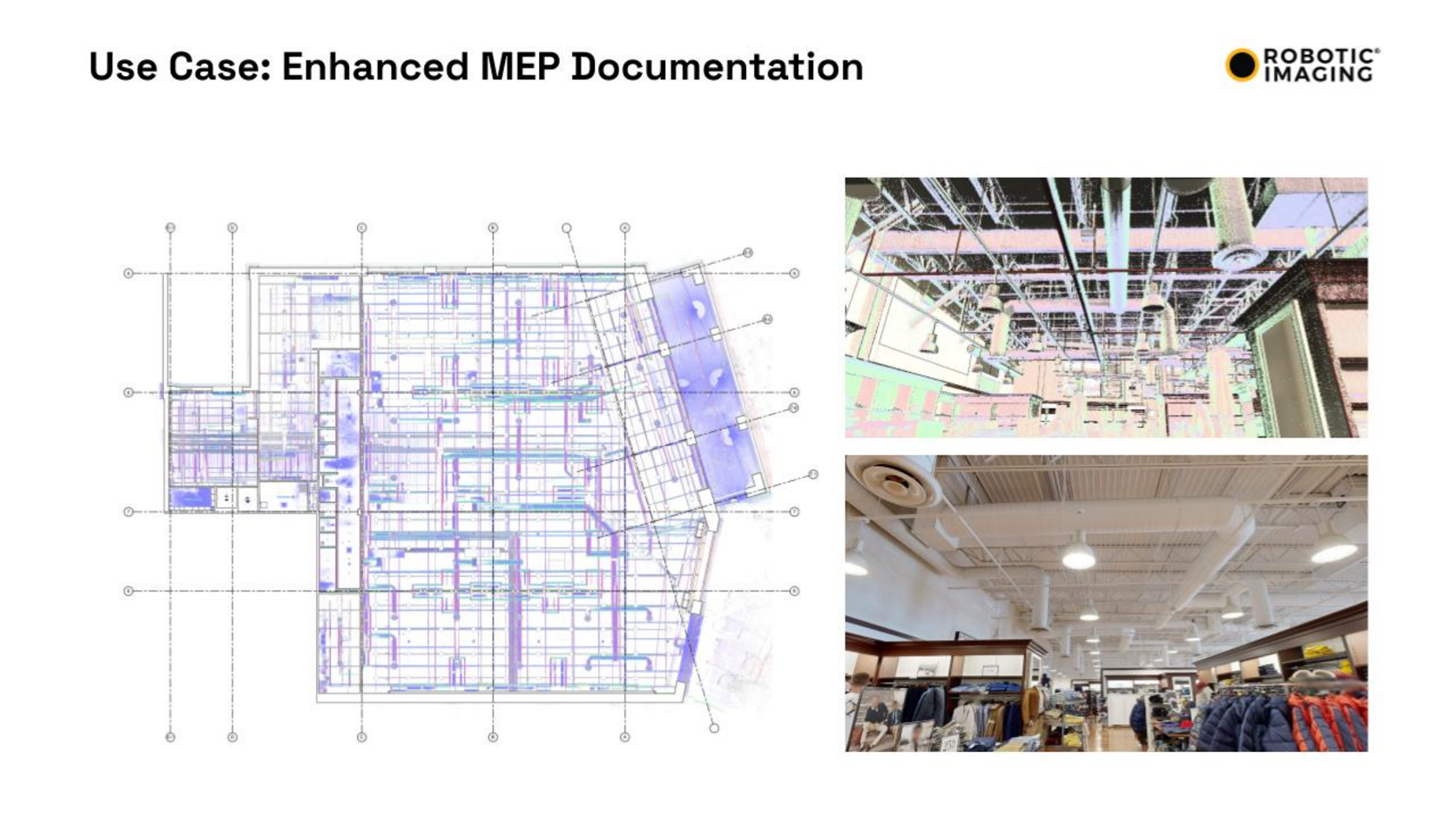
View All Deliverable Examples →The image below is an actual Robotic Imaging MEP Documentation deliverable — a real project showing the colorized point cloud overlaid on the 2D MEP floor plan, with the above-ceiling scan photograph showing exactly what systems were captured and the finished retail interior the building belongs to:
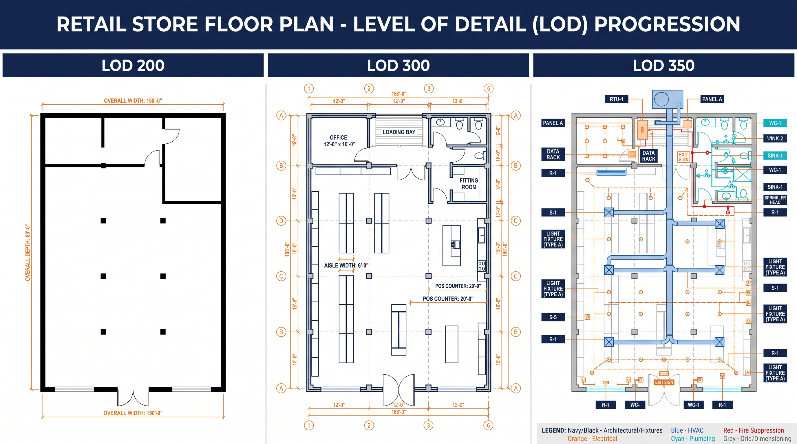
Level of Development for Scan-to-CAD: What Each LOD Means in 2D
Level of Development (LOD) defines how much detail is documented and modeled. In Scan-to-CAD, LOD governs how precisely elements are represented in the drawing, how completely MEP systems are traced, and what accuracy tolerance is maintained throughout. The right LOD depends on what the drawing will be used for downstream — not on a general preference for more or less detail.
| LOD Level | What’s Documented | Accuracy Tolerance | Typical Use Case |
|---|---|---|---|
| LOD 200 | Overall geometry, walls, major openings, approximate dimensions | ±1/4 inch from point cloud | Space planning, portfolio documentation, early cost estimation |
| LOD 300 | Exact dimensions and locations of all elements, accurate openings, precise column positions | ±1/4 inch from point cloud | Construction documentation, permit drawings, design development |
| LOD 350 | Full MEP system routing, connection points, equipment specs, system interfaces | ±1/16–1/8 inch | MEP coordination, complex renovation, facility management handover |
| LOD 400 | Fabrication-ready detail, weld locations, bolt patterns, material specifications | ±1/16 inch | Historic preservation, complex structural steel, specialty fabrication |
The LOD examples in Robotic Imaging’s service library — MEP Documentation, Space Planning, LOD 400 retail, LOD 350 facade, LOD 300 convenience store, LOD 300 building and site, LOD 300 floor plan, LOD 300 store, LOD 200 floor plan, LOD 200 elevation — reflect the actual range of projects where Scan-to-CAD is the right deliverable choice. Each represents a distinct project type with a distinct documentation need.
Scan-to-CAD by Project Type
The right LOD and deliverable set depends on the project. Here is how Scan-to-CAD maps to the most common commercial documentation scenarios:
| Project Type | Recommended LOD | Key Deliverables | Why Scan-to-CAD Wins Here |
|---|---|---|---|
| Retail store renovation | LOD 300 | Floor plan, RCP, storefront elevation | Fast multi-site turnaround, consistent accuracy across 50–500 locations |
| Commercial office TI | LOD 300–350 | Floor plan, RCP, MEP rough-in | Eliminates field verification trips, catches hidden conditions before design |
| Historic preservation | LOD 350–400 | All elevations, sections, facade drawings | Captures ornamental detail manual survey misses |
| MEP system documentation | LOD 350 | MEP plan, sections, equipment schedules | Point cloud captures above-ceiling routing without destructive investigation |
| Space planning / portfolio | LOD 200 | Floor plans, area calculations | Rapid multi-building documentation at lowest cost per sqft |
| Industrial facility | LOD 350 | Equipment layouts, piping, structural | Dense environments where manual measurement is dangerous or slow |
| C-store / convenience retail | LOD 300 | Floor plan, equipment layout, elevation | 7-Eleven, Speedway programs at scale — verified Robotic Imaging deployments |
Multi-location retail programs — convenience store rollouts, QSR renovations, retail rebrands across 50 to 500+ locations — are where Scan-to-CAD at LOD 300 delivers the highest ROI. Consistent accuracy, standardised drawing formats, and 10–14 business day delivery across simultaneous multi-site programs is what enables Robotic Imaging’s Fortune 500 retail clients — Walmart, 7-Eleven, Kroger, CVS, Nordstrom, and others — to run documentation programs at a scale that manual surveying cannot match.
Scan-to-CAD vs Scan-to-BIM: Which Do You Need?
The decision between Scan-to-CAD and Scan-to-BIM comes down to what the deliverable will be used for downstream.
Choose Scan-to-CAD when: The project requires 2D construction drawings for permitting, bidding, or renovation design. The design team works primarily in AutoCAD. No 3D coordination or clash detection is required. Budget favours the lower per-sqft cost of 2D output.
Choose Scan-to-BIM when: The project requires a Revit model because the design workflow is BIM-based or because MEP coordination across multiple trades requires 3D clash detection. The deliverable will be used for facility management after construction. The project is complex enough that a 3D model adds more value than a drawing set alone.
Both services start from the same LiDAR point cloud captured in the same 2–3 day field visit. Choosing Scan-to-CAD does not preclude upgrading to BIM later — the point cloud archive is delivered with all Scan-to-CAD projects and remains available for BIM model production at any future project phase.
Pricing and Timeline
Robotic Imaging’s Scan-to-CAD service starts at $0.19 per square foot — among the most accessible pricing for laser-scan-derived 2D documentation in the US market.
The complete delivery timeline from scheduling to final drawings:
- 2–3 days — Field technician dispatch and on-site laser scanning
- 3–5 days — Point cloud processing and registration
- 7–10 days — CAD drafting and quality verification
- 10–14 business days total — From scheduling to final deliverable
That timeline is 50–80% faster than traditional surveying for equivalent commercial scopes. For occupied buildings where floor access must be scheduled around tenants and operations, compressing site time to 2–3 days versus 1–2 weeks of traditional survey visits is a meaningful schedule advantage.
For multi-location programs, volume pricing applies. Projects covering 50 or more locations receive customised per-location pricing. Contact Robotic Imaging’s team with your location count and square footage for a program-level quote.
Frequently Asked Questions
What file formats does Robotic Imaging deliver for Scan-to-CAD?
All Scan-to-CAD deliverables come in .DWG and .DXF (AutoCAD-native, compatible with all major AEC software), and .PDF for review and permitting. Point cloud files — RCS, RCP, E57, LAS — are included with every project for downstream reference.
What is the accuracy of Scan-to-CAD drawings?
Drawings are produced from point cloud data captured at ±2–4mm accuracy. LOD 200 and LOD 300 drawings maintain a ±1/4 inch deviation tolerance from the point cloud. LOD 350 and LOD 400 tighten to ±1/16–1/8 inch. This is approximately 10x tighter than manual measurement methods.
How much does Scan-to-CAD cost?
Robotic Imaging’s Scan-to-CAD service starts at $0.19 per square foot. This covers field scanning, point cloud processing, and 2D CAD drawing production in .DWG, .DXF, and .PDF formats. Multi-location programs receive volume pricing. Contact the team with project square footage and LOD requirements for a project-specific quote.
How long does Scan-to-CAD take?
Robotic Imaging delivers Scan-to-CAD drawings in 10–14 business days from scheduling: 2–3 days field capture, 3–5 days point cloud processing, 7–10 days CAD drafting. Field technicians can be dispatched within 2–3 days of scheduling. This is 50–80% faster than traditional surveying for equivalent commercial scopes.
What is the difference between Scan-to-CAD and Scan-to-BIM?
Scan-to-CAD delivers 2D drawings in .DWG, .DXF, and .PDF formats. Scan-to-BIM delivers an intelligent 3D Revit model at LOD 200–400. Both start from the same LiDAR point cloud. Choose Scan-to-CAD when the deliverable is a drawing set for permitting, design, or renovation. Choose Scan-to-BIM when the project requires 3D coordination, clash detection, or a Revit model for downstream facility management.
What LOD levels are available for Scan-to-CAD?
Robotic Imaging delivers Scan-to-CAD at LOD 200 (approximate geometry, space planning), LOD 300 (construction-precise, permit drawings), LOD 350 (full MEP routing and interfaces), and LOD 400 (fabrication-ready detail). Most commercial renovation projects use LOD 300. See the full LOD comparison guide for detail.
Can Scan-to-CAD include MEP documentation?
Yes. MEP documentation — mechanical, electrical, and plumbing routing, equipment locations, pipe sizing, duct runs — is one of the most common Scan-to-CAD deliverables, produced at LOD 350. The point cloud captures accessible above-ceiling MEP routing during field scanning. See the real MEP Documentation deliverable example above.
Does Scan-to-CAD work for multi-location retail programs?
Yes. Multi-location retail is one of Robotic Imaging’s core use cases. The company has documented over 100 million square feet across Fortune 500 retail programs including Walmart, 7-Eleven, Kroger, CVS, Nordstrom, and AutoZone. Simultaneous multi-site deployment, standardised drawing formats, and consistent accuracy across all locations differentiate Robotic Imaging from local surveying vendors at program scale.
Get Started with Scan-to-CAD
Accurate as-built drawings are not a nice-to-have on renovation projects — they are the foundation every downstream decision rests on. When those drawings come from a LiDAR point cloud rather than a manual survey, the accuracy, coverage, and speed difference is significant enough to change project economics.
Robotic Imaging’s Scan-to-CAD service delivers that accuracy, across any scale of project or portfolio, in 10–14 business days.
Request a Scan-to-CAD quote — provide square footage, LOD, and deliverable types for a project-specific proposal.
View Scan-to-CAD deliverable samples — see the full MEP documentation, floor plans, elevations gallery before scoping your project.
Compare with Scan-to-BIM — if your project might need a 3D Revit model instead of or in addition to 2D drawings.
Explore the live platform sandbox — see how Robotic Imaging organises and delivers project documentation across a portfolio.
All pricing, delivery timelines, accuracy specifications, and client references reflect verified data from roboticimaging.com as of May 2026. Scan-to-CAD from $0.19 per square foot. Robotic Imaging is ISO 27001 certified and SOC 2 Type II compliant.