Complete Guide to Scan-to-CAD: 2D As-Built Drawing Services from LiDAR
Robotic ImagingJune 1, 2026
Complete Guide to Scan-to-CAD: 2D As-Built Drawing Services from LiDAR
Robotic Imaging’s Scan-to-CAD service converts LiDAR point cloud data into accurate, dimensioned 2D CAD drawings — floor plans, reflected ceiling plans, elevations, sections, and MEP documentation — delivered in DWG, DXF, and PDF formats at ±2mm accuracy from the LEICA RTC 360 scanner. For commercial renovation, tenant improvement, and facility documentation projects that require verified as-built drawings without the cost or complexity of a full 3D BIM model, documentation starts at $0.19 per square foot, nationwide, in 10–14 business days — 50–80% faster than traditional manual surveying for equivalent commercial scopes.
This guide covers the technology, three-phase workflow, accuracy standards, industry use cases, and enterprise-scale programs. For the full deliverable table, LOD breakdown, and project pricing, see the Scan-to-CAD service overview.
What Is Scan-to-CAD?
Scan-to-CAD is the point cloud to CAD conversion process — transforming 3D LiDAR scan data into dimensioned 2D CAD drawings. Robotic Imaging deploys the LEICA RTC 360 — which captures 2,000,000 points per second at ±2mm accuracy — in a systematic scan position sequence across a building, recording the precise location of every wall, ceiling, floor, column, opening, and MEP system. CAD technicians then extract 2D views from that point cloud: floor plans from horizontal cuts, elevations from vertical slices, reflected ceiling plans from ceiling-plane projections.
Every dimension in the finished drawing comes from a measured data point — not a tape measure or field estimate — so a building undocumented since the 1980s gets the same accuracy standard as new construction. See the Complete Guide to Scan-to-BIM Services for the broader LiDAR context.
When Should You Choose Scan-to-CAD vs. Scan-to-BIM?
Both services start from the same LEICA RTC 360 point cloud, captured in the same 2–3 day field visit. The choice is entirely about what your workflow does with the output.
| Scan-to-CAD | Scan-to-BIM | |
|---|---|---|
| Output | 2D drawings: DWG, DXF, PDF | 3D Revit model: RVT + Navisworks NWD |
| Works in | AutoCAD, MicroStation, any 2D platform | Autodesk Revit, Navisworks |
| Best for | Renovation design, permitting, bidding, space planning, facility records | MEP coordination, clash detection, BIM-based facility management |
| LOD range | LOD 200 – LOD 400 | LOD 200 – LOD 400 |
| Upgrade path | Point cloud retained — BIM model producible at any future phase from the same data | 2D views exportable from Revit model |
The point cloud archive — delivered with every project — is the same source data used for BIM model production, so this service never forecloses the BIM upgrade path. See Scan-to-BIM vs Traditional Surveying for full cost and speed comparison.
What Scan-to-CAD Delivers
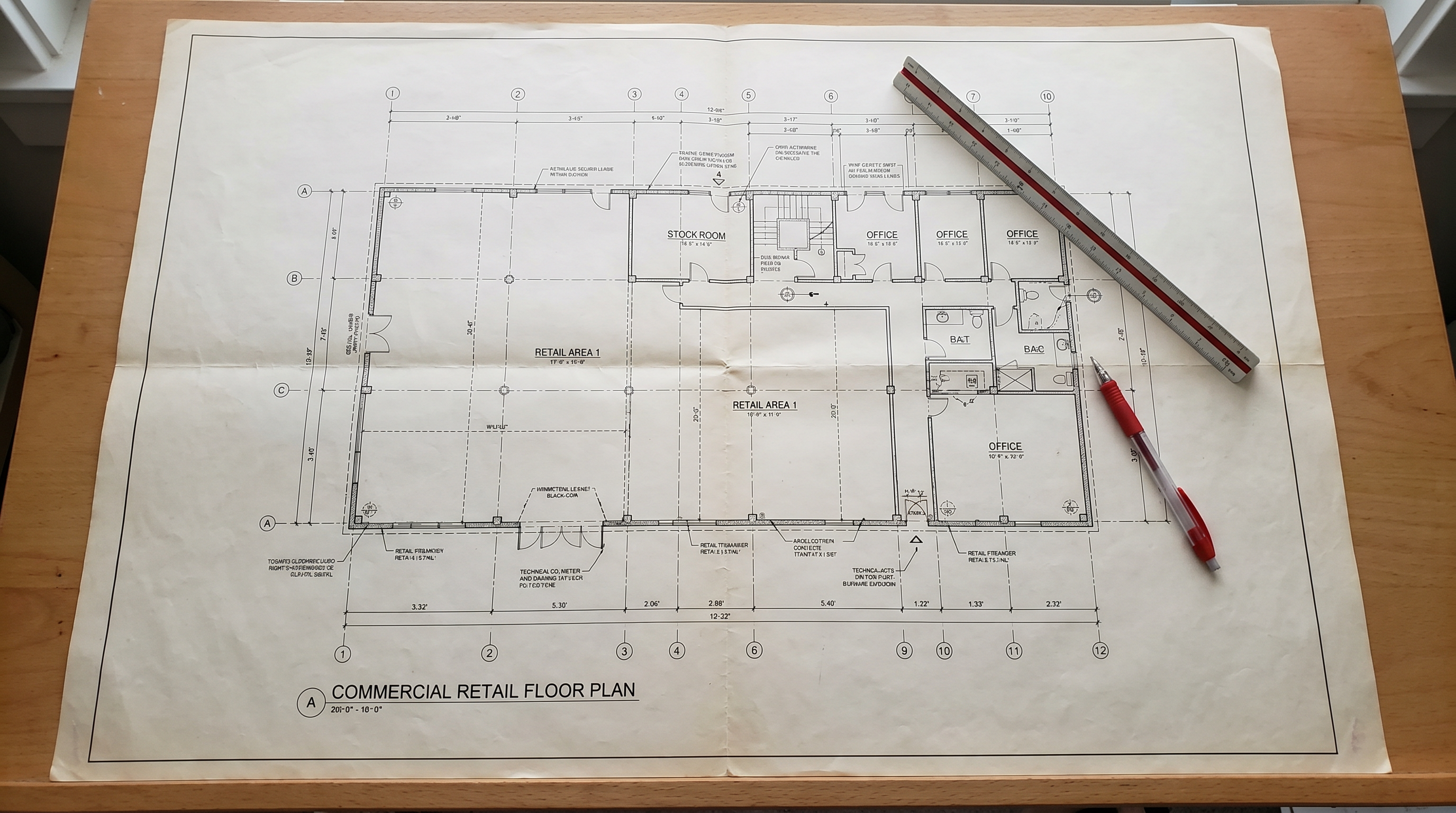
The deliverable set covers floor plans from laser scan data — reflected ceiling plans, elevations, sections, MEP documentation, space planning drawings, site plans, and facade drawings — all in DWG, DXF, and PDF, with the underlying point cloud included in RCS, E57, and LAS formats. LOD ranges from LOD 200 (space planning, approximate geometry) through LOD 300 (construction-precise, permit drawings), LOD 350 (full MEP routing), and LOD 400 (fabrication-ready detail).
Full Deliverable Table, LOD Breakdown, and Interactive Drawing Examples
Every drawing type, who needs it, LOD-to-project-type mapping, and viewable real project deliverables — MEP Documentation, LOD 400 Retail, LOD 350 Facade, LOD 300 Floor Plans, and more — are in the service overview and interactive drawing gallery.
How Does the Scan-to-CAD Workflow Run?
The complete workflow runs in three sequential phases, totalling 10–14 business days.
Phase 1 — Field Capture: 2–3 Days
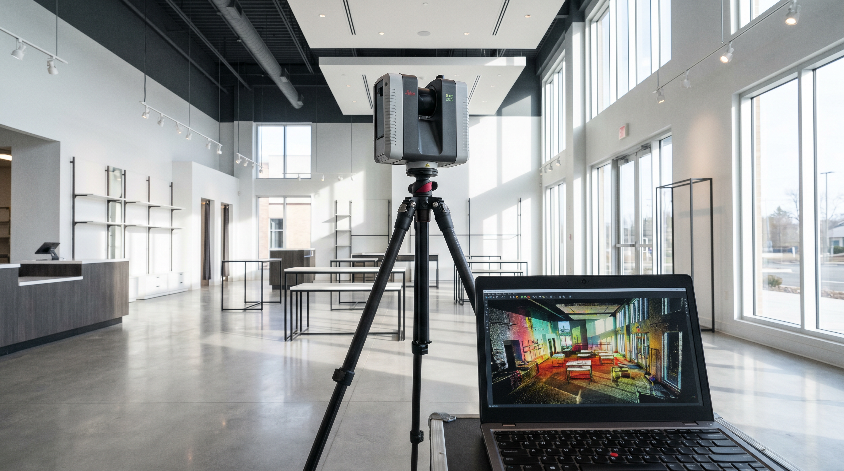
A field technician deploys the LEICA RTC 360 in a systematic scan position sequence across the full project area. Every wall face, ceiling plane, floor surface, structural element, and significant architectural feature is captured with overlapping coverage that eliminates shadow zones. For tight-access or occupied environments where a smaller footprint is required, the LEICA BLK 360 (±4mm, 60m range) is deployed. Field teams are dispatched within 2–3 days of project authorization. A single retail floor or commercial office plate is routinely captured in one day.
Phase 2 — Point Cloud Processing: 3–5 Days
Raw scan data is registered — spatially aligned into a single unified point cloud referenced to building control points — quality-checked for coverage and accuracy, then processed into RCS, E57, and LAS formats for delivery alongside the finished drawings.
Phase 3 — CAD Drafting: 7–10 Days
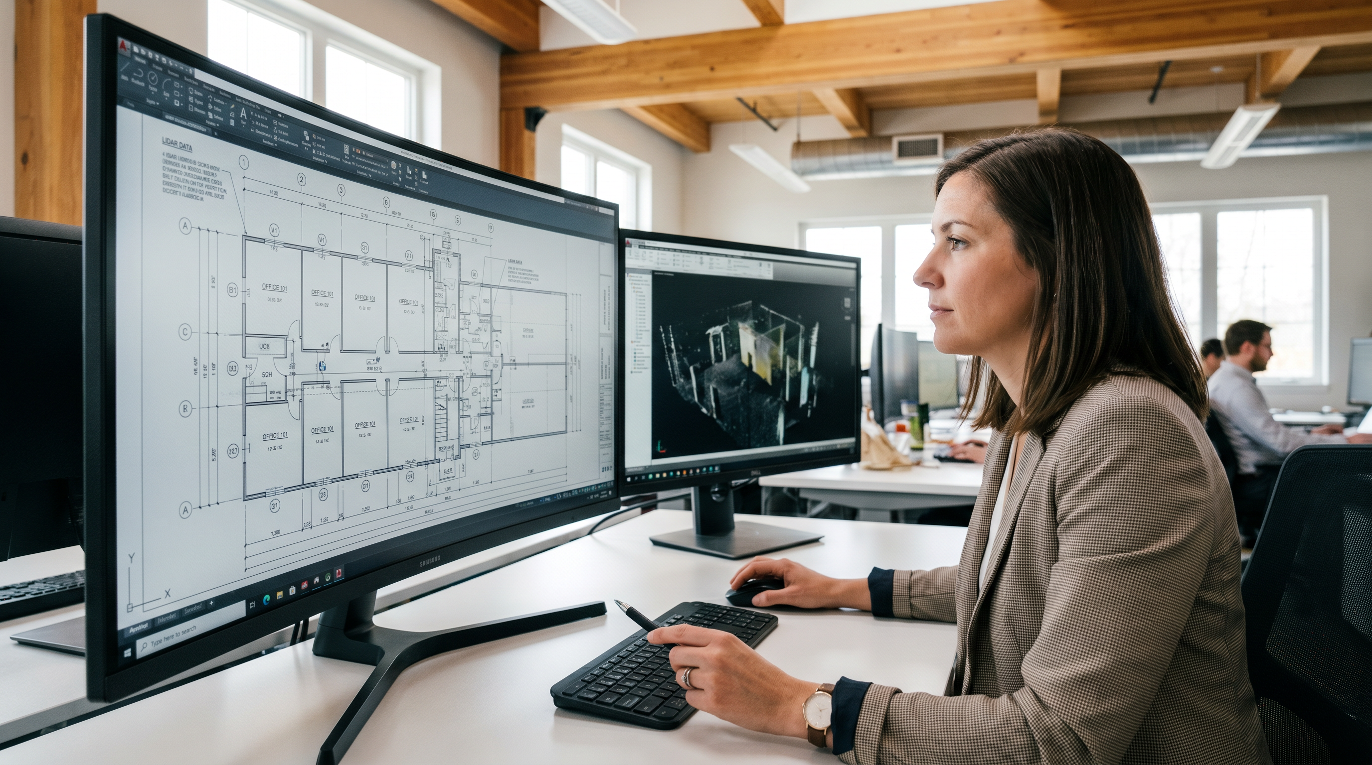
CAD technicians extract each drawing type from the point cloud — plan cuts for floor plans, elevation slices for wall documentation, ceiling projections for RCPs — tracing and dimensioning all features from measured data points. Internal QC validates dimensions and layer organization before delivery.
Accuracy: What ±2mm Means for Your Drawings
The LEICA RTC 360 captures at ±2mm accuracy (±1/16 inch) — every wall location, ceiling height, column spacing, and opening width derives from a measured data point, not a field estimate. Traditional manual documentation achieves ±¼–½ inch under ideal conditions; real-world results in occupied buildings and above-ceiling conditions are considerably worse.
At LOD 300 — the standard for commercial renovation and construction documentation — drawings maintain ±¼ inch tolerance from the point cloud. LOD 350 tightens to ±⅛–⅜ inch for MEP coordination scopes. LOD 400 achieves ±⅛ inch for fabrication-ready historic preservation and specialty structural work. See the LOD comparison guide for full detail.
That accuracy specification also matters in competitive context. Most scan-to-CAD providers operate at ±3mm to ±4mm — LiDAR equipment at that tolerance is common and less costly. The LEICA RTC 360 at ±2mm delivers measurably tighter documentation: a difference that compounds across long wall runs, complex column grids, and multi-floor dimension chains where small per-point errors accumulate into drawings that don’t match the field. For project teams who have been burned by inaccurate as-builts on previous renovations — Delta Air Lines’ Corporate Real Estate team described exactly this problem before switching to Robotic Imaging — the ±2mm standard is what eliminates downstream design verification trips entirely.
Scan-to-CAD Industries and Applications
| Industry | Primary Use Case | Why Scan-to-CAD Fits |
|---|---|---|
| Retail renovation | Remodel design, TI documentation, brand refresh across portfolio | Multi-site concurrent execution; consistent LOD 300 across 50–500 locations |
| Commercial office TI | Tenant improvement, space planning, lease documentation | Eliminates field verification trips; catches hidden conditions before design |
| Corporate real estate | Portfolio floor plan records, capital project scoping | Rapid multi-building documentation for CRE teams and FM departments |
| Historic preservation | All elevations, sections, facade drawings at LOD 350–400 | Captures ornamental detail and irregular geometry manual surveys miss |
| Industrial facilities | Equipment layouts, piping documentation, structural records | Dense environments where manual measurement is slow or access-restricted |
| C-store and QSR | LOD 300 floor plans, equipment layouts, elevation drawings at volume | Verified deployments: 7-Eleven 1,000+ sites, Speedway and similar programs |
Engineering firms including Colliers Engineering and Nelson Worldwide integrate Robotic Imaging’s Scan-to-CAD into renovation workflows, using as-built floor plans and 2D drawings as the verified existing conditions baseline. See The Architect’s Platform for As-Built Documentation for architect-specific detail.
Scan-to-CAD in practice — three client outcomes
EKahn Development (Director of Construction) — A 130,000 sq ft industrial property with no current documentation was converted to 2D line drawings and a Revit model in a single engagement, providing the verified existing conditions baseline required for adaptive reuse planning.
Puratos Inc. (Engineering & Facilities Manager) — A manufacturing plant with no existing digital drawings received accurate 2D AutoCAD drawings that directly enabled a full production floor upgrade — eliminating the manual measurement effort that would have delayed the project by months.
goPuff (Director of Real Estate) — A national quick-commerce retailer standardised its facility documentation across a growing retail portfolio, standardising drawing output across hundreds of locations.
Scan-to-CAD at Enterprise Scale
Robotic Imaging has documented 100+ million square feet since 2017. Fortune 500 programs — Walmart, Kroger, CVS, AutoZone, Ross, Burlington, T-Mobile, Lululemon — run on standardised drawing formats and consistent LOD specifications maintained across all sites and field teams.
Concurrent deployment through the 24/7 scheduling platform compresses what would otherwise be sequential documentation timelines into weeks. A 50-location renovation program that needs existing conditions drawings before design begins cannot afford sequential site-by-site execution. Simultaneous multi-location programs are standard operating procedure.
Frequently Asked Questions
When should I use Scan-to-CAD instead of Scan-to-BIM?
Use Scan-to-CAD when your design team works in AutoCAD or similar 2D platforms, when the project scope is renovation design, permitting, bidding, or record documentation, and when 3D MEP coordination or clash detection in Revit is not required. Both services start from the same LiDAR point cloud — choosing this service does not prevent upgrading to a BIM model at any future project phase.
How does LiDAR produce more accurate drawings than manual measurement?
The LEICA RTC 360 captures 2,000,000 spatial measurements per second at ±2mm accuracy — including ceiling conditions, above-grid MEP routing, column profiles, and irregular geometry that tape measures routinely miss or approximate. Every dimension in the finished drawing comes from a measured data point, not a field estimate or interpretation.
What is the Scan-to-CAD process from start to finish?
Phase 1 (2–3 days): LEICA RTC 360 field capture. Phase 2 (3–5 days): point cloud registration and QC. Phase 3 (7–10 days): CAD drafting and internal review. Total: 10–14 business days from field mobilization to finished drawing set — 50–80% faster than traditional surveying for equivalent commercial scopes.
Can Scan-to-CAD documentation be upgraded to Scan-to-BIM later?
Yes. The point cloud archive — delivered in RCS, E57, and LAS formats with every project — is the same source data used for BIM model production. If project scope changes and a Revit model becomes necessary, the existing point cloud eliminates the need for a return field visit.
How much does Scan-to-CAD cost?
Robotic Imaging’s Scan-to-CAD service starts at $0.19 per square foot — covering field scanning, point cloud processing, and 2D CAD drawing production in DWG, DXF, and PDF. Multi-location programs receive volume pricing. Contact us with project square footage and required drawing types for a project-specific quote.
What file formats does Scan-to-CAD produce?
Scan-to-CAD deliverables are provided in DWG (AutoCAD-native, compatible with all major AEC platforms), DXF (universal exchange format), and PDF for review and permit submission. The underlying point cloud is included in RCS, E57, and LAS formats — giving design teams direct access to the source scan data for additional analysis or future BIM model production.
Does Scan-to-CAD work for multi-story buildings?
Yes. Multi-floor documentation is standard. Each floor is captured with complete coverage of its ceiling, walls, and floor surfaces. Floor-to-floor heights, structural depths, and inter-floor spatial relationships are documented in section cuts derived from the registered multi-floor point cloud.
What happens if I need additional drawings after initial delivery?
The registered point cloud is retained after delivery. Additional drawing types — extra elevations, supplementary sections, or additional floor plan details — can be produced from the existing point cloud without a return field visit, provided building conditions have not changed since the scan date.
Robotic Imaging delivers Scan-to-CAD documentation at ±2mm LEICA RTC 360 accuracy, from $0.19 per square foot, in 10–14 business days, across any project or portfolio scale nationwide.
- Request a quote — provide project address, square footage, and required drawing types
- View the full service scope — complete deliverable table, LOD breakdown, and project-type mapping
- Browse the drawing gallery — interactive examples of every deliverable type from real projects
- Compare with Scan-to-BIM — if your project might need a 3D Revit model alongside or instead of 2D drawings
All pricing, delivery timelines, accuracy specifications, and client references reflect verified data from roboticimaging.com as of June 2026. Service from $0.19 per square foot. 100M+ sq ft documented. Robotic Imaging is ISO 27001 certified and SOC 2 Type II compliant.